Counterweighting methods
 In the design of crankshafts we have to incorporate counterweighting for various reasons, either for reduction of bearing loads, or to reduce or eliminate primary couples.
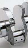
Often this is achieved through careful design of the crankshaft and the counterweights are incorporated into the crankshaft. What we aim to do in providing a counterweight is to achieve a certain moment relative to the crankshaft axis. Depending on the configuration of the crankshaft these may or may not be directly opposite the crankpin to which it is closest. The product of the mass of the counterweight and the distance of its centre of gravity from the crankshaft axis mean that the required moment can be provided with minimum mass by having the centre of gravity as far from the crankshaft axis as possible. However this strategy leads to increased inertia which causes loss of acceleration of the engine.
There is generally some restriction on the maximum radius of the counterweight imposed by adjacent components such as the base or walls of the lower crankcase or quite commonly, the combination of con rod length and the radius of the piston pin boss cause a restriction at bottom dead centre. Therefore we have to contain our counterweighting within the envelope defined by these restrictions. In many cases it remains feasible to integrate the necessary counterweighting with the crankshaft.
However, we may not be able to do this in all cases, or we may have a requirement to reduce inertia to an absolute minimum. There may be a further advantage in reducing the maximum counterweight radius to reduce the crankshaft centre height relative to the bottom of the engine. In some racing formulae this height dictates the gearbox mainshaft height and therefore has an impact on the rest of the car including aerodynamics. It is for this reason that Formula One engine suppliers invested lots of time and effort to reduce crankshaft centreline height a few years ago. Even before the development of the engine was frozen, there was a regulation introduced which imposed a minimum distance between the bottom of the engine and crankshaft axis.
In Formula One, in order to meet the required amount of counterweighting within the restrictions, it has not been possible for some time to use integrated counterweights within the same single component. It has been accepted practice in Formula One, and in a number of other applications to use heavy metal to provide the some of the counterweighting. There are now series production road vehicles using heavy metal counterweights in addition to some heavy goods vehicles.
By heavy metal we are most commonly, but not necessarily, referring to one of the commercially available tungsten alloys. These have densities which are far greater than that of steel, generally being in the range of 17,000 – 19,000 kg per cubic metre compared to approximately 7850 for steel. The FIA has again imposed a restriction in Formula One to prohibit the use of any engine materials with a density greater than 19,000 kg per cubic metre.
The options for fitting these separate pieces to the crankshaft are varied and can, by themselves, impose come other demands on the mechanical properties of the heavy metal weights and their associated components. If you are considering the use of heavy metal weights you must be sure that the method you use to secure these is reliable. The loss of a counterweight will not only damage the engine, it is a serious safety risk. Tungsten alloys are often used for armour penetration and it should be no surprise then to find that these parts can, if they become detached from the crankshaft exit the engine and the car in a pretty straight line, i.e. through the side of the engine and the bodywork or whatever else is in the way.
Written by Wayne Ward.