Cylinder liner clamping concepts
Engines that use so-called wet liners/sleeves have advantages over those that use dry liners (press-in liners in machined block material) or a parent bore (cylinder bore directly in the block’s base material). For engines with wet liners, various types of installation are possible, each of them offering their own specific advantages, such as higher coolant jacket, shorter engine length and fewer gaskets (number of possible leak paths).
When considering coolant jacket height, the mid- or bottom stop liner, which has its mounting surface located low on the liner, gives the design freedom to achieve an open-deck design and therefore to get the coolant highest up and as near as possible to the flame deck. The main aim is to have the top ring in top dead centre, as close to the coolant as possible. With modern pistons, with very little compression height, the top ring is positioned very near to the top deck and therefore the jacket design around the liner is of major importance.
An open-deck solution like the bottom or mid-stop would therefore be preferable. From the point of view of overall length, however, this design is not really preferred.
But what if your engine has a top stop liner? First, you could ask a specialist company to convert your engine block to mid- or bottom stop liners. Make sure you find a company with excellent references though, because this is a very delicate job, and if it’s not done properly it will cost you your engine.
Another option would be to check in detail how your liner has been positioned. Most engines have their liners positioned just under the liner's flange and typically have a tight radial clearance between liner and block. With this design the coolant cannot fully reach the lower side of the flange, leading to decrease in cooling of the top ring.
One solution would be to position the flange on the top diameter (flange outer diameter). This way the diameter of the liner can be decreased just below the flange, which enables coolant entry into this region. Make sure the clamping force between the head and block, which is being transferred through the flange, can still be withstood by the engine block balcony below the flange.
By creating this additional coolant ring below the flange the balcony is obviously reduced, so we need to ensure that the strength remains sufficient. One possibility to achieve the required sealing of the coolant between liner and block would be to include an O-ring groove in the outer diameter of the flange, and install a small O-ring here. This is to ensure proper sealing of the coolant to prevent leakages under the head gasket.
What should this coolant ring look like? For cooling, flow is required, so the ring should be big enough to enable flow. The target should be to achieve a ring of at least 2 mm, depending of course on the pressure drop over the ring. It might therefore be a good thing to connect the ring on one side to the highest possible pressure (directly after the coolant pump) and on the other side to the suction side of the coolant pump. That way the highest pressure drop will be achieved and the ring can be kept as small as possible, limiting the overall length of the engine.
Coming back to the sealing, one might also choose to make use of a line contact between the underside of the liner flange and the block. The benefit here is that no O-ring is needed; the downside though is that this feature might carve itself into the block structure under thermal and combustion loads (leading to micro-movements between liner and block).
If there are still cooling difficulties after these conversions, another option is to drill holes through the flange of the liner to enable flow through (and therefore also just below) the liner flange. This might require additional modifications to the head gasket and cylinder head, but that is not always possible in existing engines.
In the end though, if cooling issues remain in the top end region then it might not have been the best thing to choose that particular engine for the increased performance you had in mind.
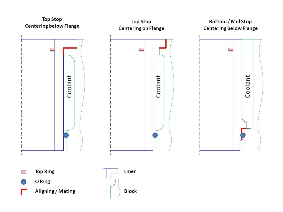 Fig. 1 - Cylinder liner concept and alignment/mating surfaces. You can see the difference in coolant height in relation to the piston top end ring
Written by Dieter van der Put
9090