Dynos: Torque Sensors
One of the key parts of a modern engine dynamometer is the torque sensor. But how do these sensors work and what recent developments have there been in sensing technology?
The vast majority of conventional systems for measuring torque operate by measuring the torsional deflection induced by the applied torque, by one of two methods: measurement of twist angle and measurement of surface strain changes.
The twist angle method of torque measurement generally requires a portion of the dynamometer’s output shaft to be reduced in diameter, to allow it to twist under load; a pair of toothed discs are then attached at opposite ends of the slim portion. The twist angle can be determined from the phase difference between magnetically or optically detected tooth/space patterns on each of the discs. Because the discs are rotating at the same rate as the output shaft, this allows for the torque to be measured at each revolution of the engine; however, the addition of extra toothed wheels at different angles could refine this measurement.
For the second method, measurement of surface strain can be achieved through the use of piezoresistive strain gauges attached to the shaft. These strains are generally too small to be accurately measured directly, so common practice is to use four gauges arranged in a Wheatstone bridge circuit. With rotating shafts, a coupling method such as rotary transformers, slip rings or local telemetry is required to feed the excitation current to the gauges and to acquire the signal from the bridge circuit in a non-contacting manner.
These sensor types are more than adequate for most dyno operations; however, their resolution is not sufficient for measuring very small torque differences, with their frequency response rarely exceeding 1 kHz. For example, if an engine is being powered by an input torque of 100 lb-ft, and the frictional losses from the bearings accounts for only 1% of the overall losses, then an accuracy of less than this is required from the instrumentation to measure the effect. This is where the latest generation of magneto-elastic torque sensors come in to play.
Magneto-elastic torque sensors produce signals that are a function of torsional stress, not strain. As a result they are generally much stiffer mechanically than the conventional elastic torque sensors. They also offer a far higher frequency response, typically of the order of 2-4 kHz. Measuring surface stress by magneto-elastic methods also provides a non-contacting system for measuring torque in a more compact construction than those required for either the twist angle or surface strain methods.
These sensors can be broken down into two separate groups, which measure magnetic quantities related to the surface shear stress in different ways. The first method measures magnetic permeability changes in the shaft surface caused by the stress-induced magnetic anisotropy affecting the permeance of a magnetic flux path, and uses a magnetising source and a pick-up (sensing) coil. These are referred to as PB Type 1 sensors. The second method is referred to as PB Type 2, where the stress-induced magnetic anisotropy causes a permanently magnetised magneto-elastically active member to generate a measurable magnetic flux.
A key advantage of a Type 1 sensor over traditional sensing methods is wireless transduction - removing the need for physical contacts with the rotating member - combined with mechanically robust construction. However, despite their various benefits, Type I permeability-based magneto-elastic torque sensors suffer from a number of disadvantages that limit their use in a testing environment. These problems derive from the fact that the variable being measured, permeability, does not depend solely on the applied torque. In any one material composition, even in a controlled environment, permeability can vary with both temperature and magnetisation. The result is that in many real-world environments, the changes due to these factors can exceed the changes in permeability that are a function of torque, making the measurements useless.
Type 2 sensors are much more suitable for use in real-world applications. They have many of the benefits of Type 1 sensors but also overcome most of the problems. The sensors can be constructed either with a thin ring of magneto-elastically active material rigidly attached to a shaft, or by using a portion of the shaft itself as the magneto-elastically active element. In response to the magneto-elastic energy associated with the bi-axial principal stresses by which torque is transmitted along the shaft, each moment will rotate towards the nearest positive principal stress direction and away from the nearest negative principal direction.
This re-orientation of the originally circular magnetisation results in a net axial magnetisation component. The divergence of this component at the edges of the polarised bands is the source of a magnetic field in the space around the shaft, which can be readily measured with one or more magnetic field sensors. This means that the problems associated with the measurement of permeability are not encountered, allowing for very accurate and repeatable readings to be taken. Additionally, the polarised bands can be easily incorporated into the output shaft of a dyno, or even into the driveshafts of a whole vehicle.
Advances such as these allow far smaller differences in performance to be accurately measured on dynos, an especially important factor in race series where power outputs can vary by factions of a percentage point.
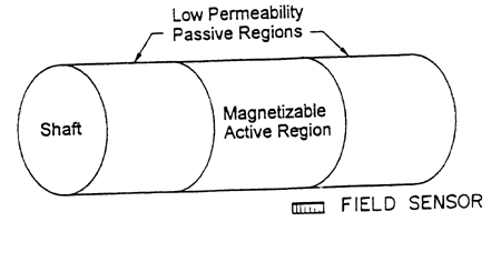
Fig. 1 - The basic layout of a shaft for use with a magneto-elastic torque sensor
Written by Lawrence Butcher
5021