Fasteners: Back to Basics - Part 3
 Last month, we looked at some basic calculations regarding cyclic loading of fasteners. Engine design engineers need a good understanding of the subject in order to correctly design the optimised fasteners required, but also those whose business is in improving the performance of engines need to be able to calculate when the standard equipment just isn’t going to be good enough.
We examined the concept of load coefficients and looked at a very simple example of how the load coefficient affects the cyclic loads in the bolt and the joint.
For the first part of the article this month, we will look at how to calculate the component stiffness for simple geometries, to allow us to calculate the load coefficient with reasonable accuracy.
The simplest possible component for which we can calculate stiffness is a straight bar of constant cross-section and, luckily, this is pretty much what a lot of fasteners are. For more complicated fasteners, we can model these with reasonable accuracy as a number of constant cross-sections in series. If we want to imagine how this might work, we should think of our spring analogy with a stiff spring and a less stiff one placed in series (stacked one on top of the other). If we apply a load to them, they both experience the same load and both deflect, but the less stiff one deflects more than the stiffer one.
We might remember from physics or engineering classes the concept of elastic modulus (often referred to as Young’s modulus after the British engineer of the same name), which is basically a measure of stiffness of a given material. It is defined as the ratio of stress to strain.
E = s/e
where:
E = elastic modulus (units of Newtons per metres squared)
s = stress (units of Newtons per metres squared)
e = strain (dimensionless)
Stress is the ratio of force to normal cross-sectional area, and strain is the ratio of change in length to original length, i.e.:
s = F/A
e = ?L/L
If we substitute these definitions into the formula for elastic modulus, we get:
E = FL/A ?L
The component stiffness, k is the ratio of force to elongation or change in length, i.e.:
k = F/ ?L
Therefore, we can, by re-arranging the equations see that:
k = F/ ?L = EA/L
This makes sense as we can imagine that a bar of large cross-sectional area deflects less under a given load than a smaller one. Those who, through practical experience, understand how springs behave know that a longer spring of otherwise identical dimensions (same coil spacing, wire diameter and mean diameter) and material will deflect more under the same load.
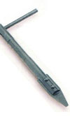
For a more complicated geometry, for example where there are shoulders etc on the bolts (see the attached picture of a shoulder bolt), we simply treat this as three simple columns in series – the main part of the shank, the increased diameter and the thread, which behaves as a reduced diameter. Some people consider the thread diameter to be the minor (root) diameter, and others consider it to be the mean of the minor and pitch diameters. The second case is the more conservative, giving a larger load coefficient.
For two or more columns in series, with stiffness’ k1, k2 etc, the formula to calculate the overall stiffness is:
1/kt = (1/k1) + (1/k2) + (1/k3) + …..
Next month we will look at joint stiffness which will then allow us to calculate load coefficient.
Written by Wayne Ward.
3494