Harvest festival
First introduced in 2009 and then after a year’s absence again in 2011, energy efficiency in Formula One is set to take a further step forward in 2014. Initially called KERS (Kinetic Energy Recovery System) the concept of energy recovery is being widened to the more generic description of ERS (Energy Recovery System). Thus, and seemingly at a stroke, the new regulations will improve the image of Formula One from simply an irrelevant ‘waste of time’ to a much-needed r&d tool for the hard-pressed road-going vehicle manufacturer.
And so, by allowing teams to ‘harvest’ other forms of wasted energy on the vehicle, rather than being simply a tyre-shredding spectacle relying on aerodynamic downforce, from 2014 Formula One will be all about efficiency – efficiency in the generation of engine power, and at the same time efficiency in using it.
Under the current rules, energy recovery from the 2.4 litre V8 engines has been restricted to the use of a single device, a motor/generator (otherwise known as an e-machine) or (in theory at least) a flywheel arrangement, capturing energy under vehicle braking. Subject to a recovery rate of no more than 2 kW and a release rate of no greater than 60 kW, this is released for a maximum of 6.67 s per lap at maximum power output. Such a system, while potentially great for overtaking and thus adding to the spectacle, has little real benefit in the road vehicle world.
For 2014, however, the rules are much more far-reaching, for in addition to a limit on the fuel flow rate and the ability to capture the vehicle’s kinetic energy, the energy that might otherwise be wasted in the exhaust gas of the now 1.6 litre turbocharged unit can be harnessed as well.
So as well as doubling the power of the e-motor directly to the engine and a tenfold increase in the amount of energy released per lap (up to 4 MJ), teams have the ability to harvest as much energy as they wish from any left over in the engine exhaust system by introducing yet another e-motor attached to the shaft of the turbocharger.
And so from a period when getting as much air as possible into the engine was the guiding principle, the introduction of a fuel flow limit of 100 kg/h and a maximum tank size of 100 kg moves the formula to a place where maximum fuel efficiency is the aim.
This introduces a number of options for the engine designers, and yet more so for the teams during the race. Computer modelling of the systems so far has indicated that the KERS unit will be operating for much of the time. The power for this will come partly from the energy harvested under braking but mostly from that harvested from the e-machine linked to the turbocharger. At times during the race, excess energy will be harvested from the turbocharger turbine to top up the battery energy store. At other times, however, at low engine speed say, the energy from the battery could be used to spin up the compressor to maintain the boost.
This latter could encourage engines to run at lower engine speeds than the maximum of 15,000 rpm, where friction is lower, efficiency is higher and the amount of heat rejected into the atmosphere through heat exchangers much less. And whereas current 2013 engines work best at minimal exhaust back-pressures, future V6 turbocharged units will experience greater back-pressures and may need to be less sensitive to them, so as not to downrate performance.
But whatever approach is used, things like the aerodynamic set-up (and hence drag of the vehicle), the heat rejected from the engine and the sensitivity to the increased back-pressures generated – not forgetting of course the amount of fuel still left in the tank – will all feature in the race strategy.
If all this is uncertain, of one thing I am sure: there will be road vehicle power unit designers all over the world looking at the outcome.
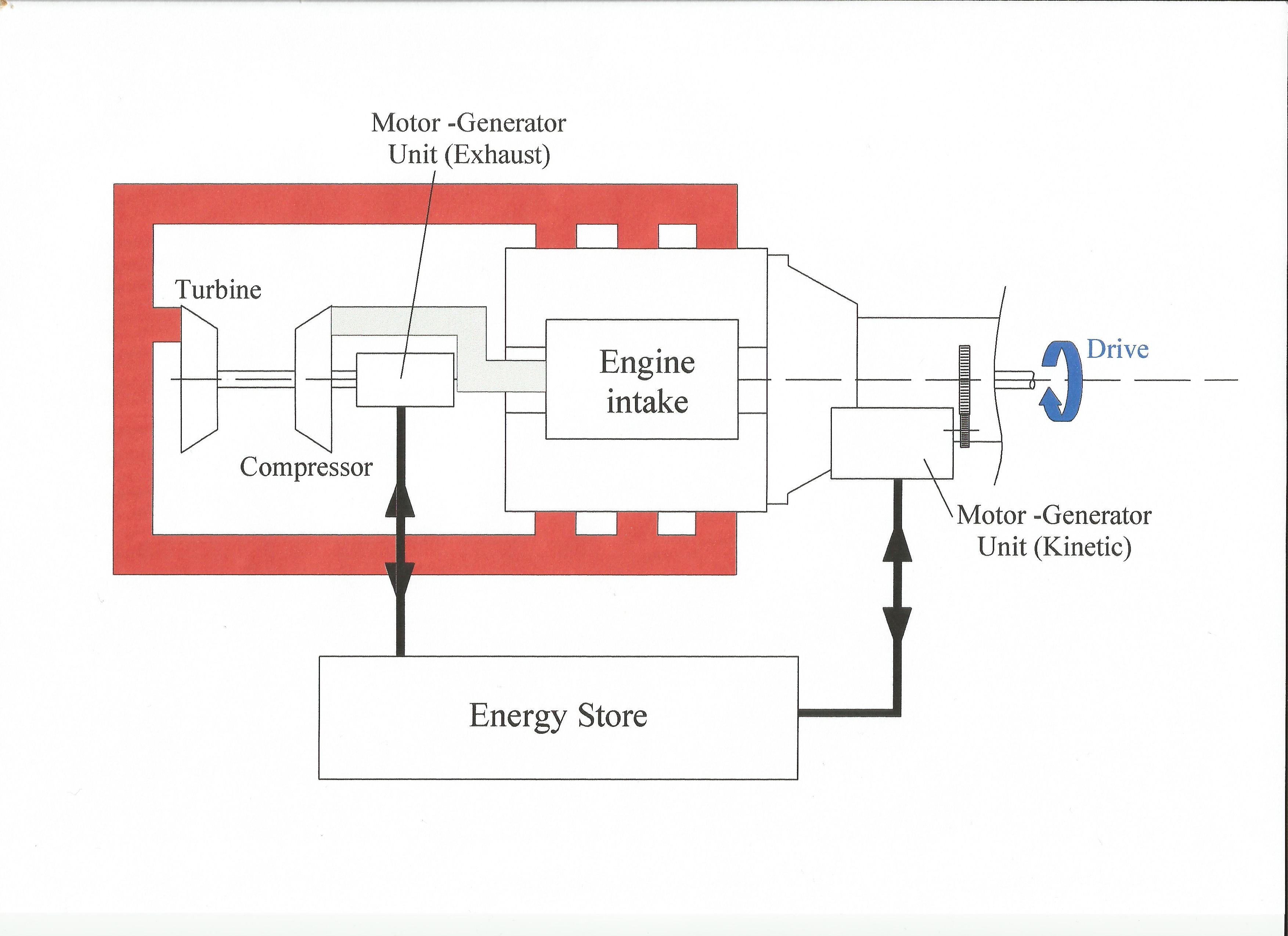 Fig. 1 - Formula One engine schematic for 2014
Written by John Coxon
4144