Hot head?
 In my previous Heads-Blocks article I described the advantage of Compacted Graphite Iron (CGI) on one of the most severe cylinder head failure modes, Thermo Mechanical Fatigue (TMF). The main area of interest then concerned differences in material properties. Of course, material is not the only contributor to TMF robustness of cylinder head design, so in this article I will give an insight into another parameter influencing TMF, coolant jacket design.
As mentioned previously, a cylinder head is loaded in many ways. In general, there are three different loads - assembly load, (peak) firing pressure load and thermal load. A combination of these can lead to failure of the cylinder head, TMF.
What usually happens is that the heat loading of the cylinder head leads to expansion, which cannot take place fully due to the constraining cylinder head bolts (or studs) with which the head is mounted to the block. Constraining the expansion will lead to internal damage of the material (plastification by compression) which, when the engine cools down, is transferred into tensional stress.
When this cyclic loading of compression and tensional stresses exceeds the maximum permissible tensile stress limit of the cylinder head material, cylinder head cracks form. Most cracks occur in the valve bridge area between the intake and exhaust valve seat rings, partly because of the minimal material width of the valve bridge but mainly because of the high degree of constraint in the longitudinal direction of the cylinder head. Typically the transverse direction has less constraint due to the lack of adjacent cylinders in that direction. This, in summary, is the failure mechanism behind TMF.
Besides the design freedom concerning cylinder head material, there some other areas of freedom in designing for robustness against TMF. In this article the influence of the design of the cylinder head coolant jacket will be further clarified.
Let us look at how a coolant jacket is designed in the first place. A coolant jacket in the cylinder head is nothing more than a consequence of the rest of the component arrangement in the cylinder head.
Take the example of a common four-valve DOHC cylinder head. The double overhead camshaft automatically leads to a parallel valve pattern, meaning the intake and exhaust valves are oriented in the longitudinal direction of the cylinder head. Mostly the in- and exhaust ports are in this case are designed opposite each other, and a logical choice for the number of cylinder head bolts is four or six, depending for the most part on bore size and block and head structure.
Other components of interest are the valve guides and, even more so, the valve seat rings, in order to have a robust valve seat area. And last, but not least, the spark plug needs its place, almost always located centrally between the four valves and protruding perpendicularly into the combustion chamber.
Take these structural boundary conditions into account and one can see that the available space left can be used as coolant jacket. Therefore, the only real design freedom is where to locate the intake and return of the coolant jacket, the choice between a single or double water jacket and the choice between a cross-flow or longitudinal flow of the coolant. Due to the heat rejection of highly loaded race engines, most designs incorporate a cross-coolant flow, meaning flow from exhaust side to intake side or vice versa.
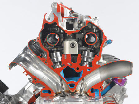
Having said this then, what is the relation between coolant jacket and the mechanism of TMF? To answer this, an additional constraint needs to be explained, that of the flame deck of the cylinder head.
The flame deck is the side of the cylinder head side that is in direct contact with the combustion chamber. It needs a certain thickness (strength) to resist the combustion loading, or so-called peak firing pressure. Roughly speaking, the peak firing pressures of race engines will lie in the range between about 100 and 250 bar, varying between naturally aspirated and turbocharged engines, and both diesel and gasoline.
The combustion loading will try to push the flame deck upwards. In order to withstand this deformation, the deck needs to have a certain minimum thickness. However, to reduce the risk of TMF, the temperature of the material needs to be kept as low as possible, meaning as little material as possible between combustion gas and coolant jacket.
This is exactly where the conflicting demands on the flame deck can be seen. Typically the flame deck thickness is a consequence of the diameter and height of the valve seat rings, requiring sufficient base material around them to achieve the required press fit. Between the seat rings in the tightest section - the valve bridges - there is often insufficient coolant available to reduce the risk of cracks. As long as these cracks do not progress into the water jacket, there is no problem. Otherwise, however, coolant will leak into the combustion chamber.
In the next article I will take a more detailed look at TMF and cylinder head design.
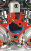
Fig. 1 - RVX-09 coolant jacket
Written by Dieter van der Put
5211