How Many is a Crowd?
In this month’s article we will take a look at how engine designers arrive at the number of cylinder head bolts in their engine designs and the compromises they need to make in getting there.
Looking at a broad range of engines, not just high-performance race engines, one sees a wide variety in the number of cylinder head bolts in the different designs. Look a little further the reasons for this are obvious. Typically, the number of bolts is a consequence of some other, higher-priority decisions.
Let us start from the beginning. The reason cylinder bolts exist is purely because the cylinder head and block need to remain together under combustion load. Apart from that they have no added value whatsoever to a running engine. Given the size of these bolts in relation to the bore, one can see that significant amounts of material needs to be reserved for them. That means these areas cannot be used for other functions of the cylinder head, such as the intake and exhaust ports, coolant cavities, injector and spark plug bores. Also, the interfaces between head and block need to be located somewhere outside the bolt areas.
Historically, the number of cylinder head bolts used in engine design has varied between four and eight per cylinder, although of course adjacent cylinders make use of the bolts in between. So, when one calculates the number of bolts, for example to calculate bolt loading, one should correct for this and reduce by two bolts (four halves) per cylinder. To achieve optimum roundness of the cylinder bore, the advantage would go towards using more, smaller diameter bolts. The overall clamping load in this case will be divided more evenly over the circumference, leading to a lower deformation of the bore itself, enabling improved - as in more homogenous - contact between piston rings and liner, meaning less friction and an increase of effective power.
Bolt size and material specification are chosen according to bore size and maximum cylinder peak combustion pressures. The intake and exhaust ports are often the largest features that need to be incorporated in between the cylinder head bolts. Engine engineers have two choices - either one bolt in between the two intake ports, or a bolt on either side of both ports.
When the engine is a derivative of a production unit, all bolts need to be accessible from the top. The background here is of course mass production assembly, where process time is of major importance. Some engines, specifically designed for racing purposes, are known for making use of cylinder head bolts entering the cylinder head from below, mostly the bolt located nearest to the intake ports. In this case the intake ports can be designed without taking this bolt into account, leading to a more optimum port shape. However, with this type of bolt location, accessibility to these bolts will be unfavourable, to say the least.
On the exhaust side the engineer faces a similar challenge, although the extreme heat loading of the exhaust gases makes life even more difficult here. It’s impossible to engineer a bolt in between the exhaust ports, since the material around it cannot be cooled sufficiently. The limited area available does not allow coolant to get near this bolt, and this can lead to temperature cracks and other thermal-related issues.
The last possible interference with cylinder head bolts are fuel drillings, in the case of in-cylinder injection, either direct gasoline(-like) injection or diesel injectors. Mostly with diesel-powered engines, a (high pressure) fuel line drilling needs to be incorporated into the cylinder head. Where an intake or exhaust port could be designed to be slightly curved, a drilling requires straight-line access to the injector.
In summary, fewer cylinder head bolts give more design freedom in relation to the other features inside the cylinder head. However, more bolts will provide lower distortion of the bore, leading to other, more friction-related advantages.
And so this brings us to the engineering conclusion we have shared many times already: engine design does not know ideals, only well thought-out compromises.
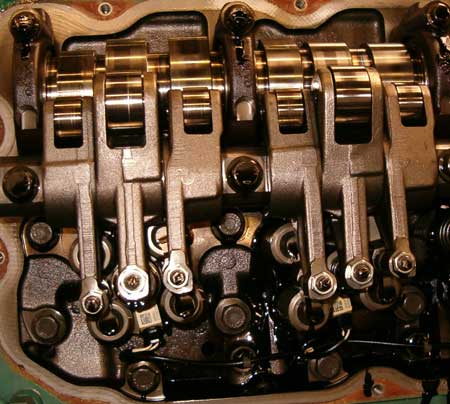
Fig. 1 - Top view of the cylinder head of a truck engine: plenty of features in a relatively small area
Written by Dieter van der Put
3281