Lessons in liners
 As engineers we all have a lot to learn, and no matter how long we have been in the business, I am sure there is no-one out there who will not claim to be learning still. Take this lesson from the history books for instance.
For many years it has been accepted practice to locate wet liners via a recess in the cylinder block top deck and seal between the outer liner surface and the cylinder block casting at the base of the liner using a system of 'O' rings under compression. Clamped at the top by the cylinder head and fire ring, the liner is free to expand both vertically and diametrically, and yet still maintain a positive seal with the water jacket at both top and bottom. The seal at the top is maintained by the clamping load of the cylinder head pressing the lip of the liner into the softer surface of the aluminium block, while that at the bottom is classic 'O' ring practice.
The downside with this method is the restricted level of cooling around the top of the liner and the effect that this can have on combustion. Years ago, however, respected Formula One engine supplier Coventry Climax used another approach - at least for a short time.
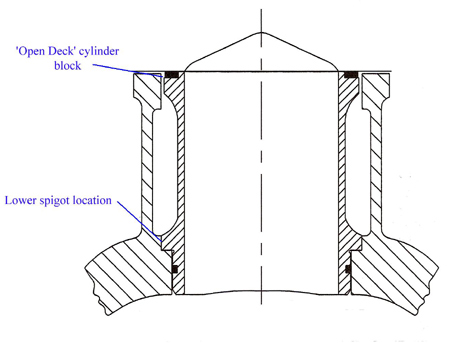
In order to obtain maximum cooling around the top of the liner on its prototype FWMV 1.5 litre V8s, and create what is known as an 'open deck' design, the company located the cylinder liner in a spigot some way down, about 3in (75 mm) inside the cylinder block. Clamped against a ledge at this lower location and sealed at this point using traditional 'O' ring practice, the liner was clamped at the top by the cylinder head, combustion being sealed with a Cooper's ring. Using cast-iron liner technology within an aluminium cylinder block, all went well with the engine on the dyno.
The normal testing procedure with prototype engines of this type is for a progressive warm-up phase followed by lots of wide-open throttle testing at a constant temperature. The procedure gave no hint of the problems to come, however, and it was only when the engine was installed in a car that the issues began to show.
Although it ran perfectly well on the dyno, once installed in a car the engine would soon blow all its coolant out of the radiator header tank. Stripping the engine revealed no obvious failure, but in time the real reason for the phenomenon became apparent.
Locating the liner at the lower position allowed the effects of the differential expansion to affect the clamp load at the fire face. While the gradual warming of the engine on the dyno kept this clamp load under control, once installed in a car the rapidly changing thermal loads, the different expansion coefficients and thermal conductivity soon provided the exact conditions to take away this clamping pressure. Combustion gas then quickly found its way into the coolant system, pushing the coolant out of the header tank.
In this particular case, after much deliberation the eventual solution was to move towards a dry liner system using aluminium sleeves into which the turned-down iron liners were pressed. Effectively located at the top of the cylinder block now, coolant loss through the header tank was a thing of the past.
It was a hard lesson to learn, and one I am sure the engineers at Coventry Climax were never to forget.
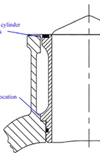
Fig. 1 - The flawed design
Written by John Coxon
3494