Managing brake cooling flows
Under braking, the friction of the brake pads against the disc transfers the kinetic energy of the car into heat, which passes through the brake disc, pads and caliper. Unless this energy can be removed from these components then eventually they will fail, and there are three main mechanisms through which this heat can be dispersed – convection, conduction and radiation.
By far the most efficient method of heat transfer from the brakes is through convection. This is achieved by blowing cold air over a hot component – usually the disc, pads and caliper – as well as any nearby electronic sensors. The plethora of vented brake disc designs, with their large number of flow paths drilled or moulded radially through the disc, are designed to increase convection. As flow passes through these holes, heat is transferred from the hot disc into the colder air, and as this flow heads out of the wheel it can be up to 400 C hotter than it went in.
The brake discs must be run at around 400 C (although peak temperatures may hit 1200 C at points in the lap). Too hot and they rapidly oxidise, resulting is excessive wear; too cold and the braking performance is poor. Teams alter their cooling set-up on a race-by-race basis, using a range of inlet sizes, using taping or blanking for fine tuning.
An easy way to increase the cooling level is to increase the mass-flow through the brake duct. This can usually be achieved by increasing the inlet size of the duct, but that usually leads to worse external aero performance. Contrary to popular opinion, it is not the drag from a large inlet scoop that is detrimental to the car’s performance; rather it is the effect of the larger duct on the myriad of flicks, winglets and flow-conditioners that surround it. In general, minimising the size of the cooling inlet for a required cooling level leads to greater aero performance, and this can be achieved through the design of the internal ducting and brake disc.
Historically, all high-temperature flow is expelled from the outboard side of the wheel without further use. However, the temperature-sensitive performance of the Pirelli tyres over the past couple of seasons has led teams to experiment with redirecting the hot flow coming out of the brakes as a way to affect tyre temperature.
The only component of the car in direct contact with the tyre is the wheel rim, which provides a conduction path into tyre’s carcass. The external surfaces of the wheel rim, within the tyre cavity, face the internal surfaces of the tyre, which allows it to be heated through radiation from the inside. Heating up the wheel rim can give a small but measurable increase in tyre temperature and, vice versa, cooling the wheel rim can reduce tyre temperature.
The leading teams pursue a strategy of heating the front wheel rims, particularly to increase front tyre temperatures for qualifying. One mechanism that has been used by several teams is to remove a large amount of the brake shroud and directly expose the brake disc to the inside of the wheel rim. When combined with surface coatings on the inside of the rim, this can lead to significant increases in rim temperature through radiation.
The aim with the rear wheels is to generate a cooling effect – or at least minimise any heating effect from the brakes – to avoid the dramatic drop-offs in race performance experienced by some teams as a result of overheating the tyres. In an effort to control their rear tyre temperatures, the teams take steps to isolate the brakes from the wheel rim, including:
- The brake disc is contained with a carbon shroud, accurately controlling the hot and cold flow paths
- All the hot brake disc flow can be ducted back out inboard of the wheel, preventing it from passing over the wheel rim
- Channels are recessed into the brake shrouds, allowing cold flow to be directed into the small air gap between the shroud and the wheel rim, and helping to isolate the wheel rim.
Development and simulation of the brake cooling flows is primarily conducted using a combination of physical dyno testing and CFD. Track testing is too limited, and wind tunnel testing of components within the wheels is problematic because of the need to accommodate load cells, part modularity and clearances. CFD has the advantage of being able to model and separate out the importance of the various levels of physics at work. Brake components, in particular discs and calipers, are usually tested on a full-size test rig over an entire race simulation before being signed off for use on the racecar. Data from this testing is fed back into the simulation process.
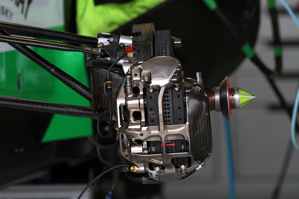 Fig. 1 - The most efficient method of heat transfer from the brakes is by blowing cold air over hot components such as the caliper (Photo: Michael D)
Written by Rob Lewis
6893