Solving pushrod fitment challenges
 While pushrods may not have a place in (relatively) unrestricted, top-flight racing engines any more, they are still a part of the racing landscape in many forms of racing, whether by regulation or through financial expediency.
NASCAR, of course, mandates the use of a pushrod engine in all its racing series, along with a single block-mounted camshaft and a controlled height above the crankshaft. Like almost every part of a racing engine, pushrod design is the subject of a number of opposing requirements and constraints, making optimum design difficult to achieve.
With any high acceleration valvetrain, low mass is critical, as the cam motion must force open the valve against its own inertia. It has to provide the force to oppose the closing spring force and must also provide the force to rotate the rocker mechanism and accelerate the pushrod and tappet/lifter. As the cam rotates, the force across the cam-tappet interface is one of the fundamental limitations.
This interface can take only so much surface stress, so if you can make the pushrod lighter, there is more force available to accelerate the valve at a higher rate, potentially releasing more power.
Still, there are plenty of other constraints working against a lightweight pushrod. High stiffness is one of the most important, and is normally associated with stiff material. The bending stiffness has to be sufficient to prevent buckling failure, and both the bending stiffness and the compressive stiffness will be significant when it comes to looking at the whole valvetrain's dynamics.
A big part of the analytical and/or testing work on a pushrod valvetrain will be to understand, control and minimise these loads across the working rev ranges, in order to avoid excessive amounts of vibration in and through the valvetrain that cause excessively high loads.
A typical solution for high stiffness and low weight in engineering would be a thinner wall at a larger diameter, but in most instances pushrods compete for space in the cylinder head with the intake port. The cylinder head designer is constantly squeezing the valvetrain designer for space, and vice versa. Bends and bumps in ports are often the result for the cylinder head design, so a clear constraint in terms of maximum diameter and offsets to straight runs for the pushrod/tappet are the result for the valvetrain engineer.
The next crucial part of the pushrod is the ends. All the force going through the pushrod to open the valve has to go across the two miniature contact patches at each end of the rod. As with the cam-tappet interface, there is only so much surface stress that can be taken - so again, materials, accuracy of surface forms, surface finishes, treatments and lubrication become crucial issues. The result is also that the optimum material properties required at the tips are often different from the optimum material requirements for the rest of the pushrod.
For this reason, pushrods are often two- or three-piece devices with precision made, hard end pieces. Still, as a new piece is introduced, it introduces another component-to-component interface to get right and the load has to get across each one of these new interfaces, too.
Next time: dealing with pushrod adjustments, and overall cost
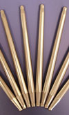
Fig. 1 - Pushrod display
Written by Anne Proffit
3124