Taking the heat
That the average gasoline-fuelled race engine is no more than about 28% efficient is a source of great angst to many power unit engineers. But while the best will claim 37-38% and the worst nearer 20%, the inescapable fact still remains that the vast majority of energy available from the fuel is lost in the form of heat.
Split evenly between heat in the exhaust gas and that delivered up to the cooling water jacket, that means for a 450 kW race engine somewhere in the region of 500 kW of heat is rejected to the coolant - that's roughly 160 three-bar electric fires, as my old thermodynamics lecturer used to say! And all this has to be dissipated into the surrounding air in as efficient a way as possible.
But in designing a cooling system there are certain limitations. To start off with, the temperature difference across an engine when running at full load from the inlet to the coolant pump to the outlet of the cylinder head should be no greater than 3-5 C. Anything greater than that risks unacceptable thermal gradients across and through the unit, leading to extra strains as well as problems with combustion. The coolant flow rate through the engine should be such as to maintain this. And if the temperature rise across the engine is 3-5 C then by the conservation of energy and the fact that the coolant flow rate is the same for both engine and radiator, the temperature fall across the cooling system will also be around 3-5 C. The role of the radiator therefore is to dissipate all this heat in the most efficient way with the minimum mount of weight.
As an efficient conductor of heat, copper has few equals, but its specific density of 9 g/cm3 make it too heavy for most automotive uses. For modern vehicle radiators, especially those used for motorsport, aluminium (density 2.7 g/cm3) is the only option, while anything culled from an OE manufacturer's parts bin will almost certainly have plastic end caps clamped at either side.
Within the core of the radiator there are two types of construction. The first and most common for automotive use is the so-called tube and fin arrangement. Consisting of thin (2 mm) oval-shaped tubes running between inlet and outlet end caps, these tubes are separated by thin corrugated metal sheeting. Providing hugely increased surface area while at the same time producing a radiator core that is mechanically stiff, these are produced in standard core sizes of 22, 32, 42, 55, 66 and even 86 mm widths with fin densities of between 14 and 24 fins per inch.
Spaced at anything between 7 and 10 mm apart, the size (cross-sectional area) of the radiator matrix depends on the vehicle aerodynamics and the allowable drag induced, while the thickness of the core is a function of the heat to be dissipated. The greater the cross-sectional area of the matrix, the better the heat dissipation but at the expense of aerodynamic efficiency. And the thicker the core, the less efficient the heat transfer and the heavier the solution. As in everything engineering today, specifying a radiator design is all down to the compromise between cross-sectional area and core thickness.
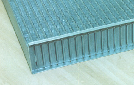
The other core matrix design, and the one most used in high-level motorsport because of its design flexibility, is the plate and bar design. Presenting many advantages over the tube and fin approach, this radiator design can not only be externally baffled but internally baffled as well to increase the wetted area and improve the heat transfer coefficient between coolant and the radiator material. Typically two or three times more expensive than the fin and tube design, for performance at minimum weight they are however the racer's first choice.
Fin and tube, bar and plate: in the process of designing your cooling system, choosing the core of your radiator is only the first of many decisions to be made.
Fig. 1 - Typical fin and tube core
Written by John Coxon
3435