Testing radiators for heat dissipation
There are a number of ways to evaluate the heat dissipation performance of a radiator. Some might prefer a computational approach using one of the many CFD codes available to model heat fluxes and fluid flows. However, since the geometry of a radiator is complex, requiring large amounts of computing power and detailed knowledge of how to use the software, this might be the least preferred approach, except by the CFD specialist with a suitable budget and the desire to get down into the detail.
Another analytical method of course is to use tried and tested mathematical formulae. The Log Mean Temperature Difference (LMTD) is a popular calculation here, and relies on knowledge of overall heat transfer coefficients, the effective surface area of the radiator, a correction factor (sometimes referred to as an ‘ignorance’ factor) and a parameter called the LMTD of the two fluids in use.
A third method much along the same lines expresses the heat transfer in a different way: the difference in temperature between the air and the radiator wall, the surface area, the local air velocity and the type of radiator typified by its ‘K’ factor. From this we could calculate the heat dissipated – assuming, of course, the ideal condition where there are no leaks and the mass of air flowing is constant. The K factor of a radiator is often developed from tables of similar designs, but what if you don’t know your K factor or if your radiator is not of a traditional size or shape? Obviously you could wait for it to be installed and tested in situ in a vehicle and never know if its poor performance was down to its design or installation. Failing that, you could use some kind of radiator test rig or wind tunnel.
A radiator wind tunnel is fundamentally different from one used to test the aerodynamics of vehicles. The most obvious difference is that radiator rigs will generally have a much higher blockage factor, since all the airflow will be channelled through it. This effectively dictates the type of fan that can be used. In vehicle ‘aerodynamic’ tunnels the blockage factor of the car under test is comparatively low, and the pressure drop across the test section is consequently also very low or non-existent. The type of fan preferred will be that of an axial flow ‘air mover’ situated after the test section to avoid introducing turbulent flow to the vehicle or model. A radiator tunnel, however, filling the whole cross-section of the test item, will have a comparatively large pressure drop across it, and will therefore be more suited to the characteristics of a centrifugal blower, which will need to be placed in front of the test section.
Unfortunately the airflow of such a fan is far from uniform, and any turbulence induced by the rotating blades needs to be corrected and ‘straightened’ out to present laminar flow to the radiator. This is most efficiently achieved by slowing the air down through a diffuser and passing it through some form of ‘flow straightener’. The angle of this diffuser can be quite critical to avoid flow separation and the localised turbulent flow that results. At the same time, space is often at a premium and so a compromise of around a 15-20º taper is often used.
After the diffuser comes the settling chamber. Designed to dampen out the last dregs of swirl from the airflow and create a uniform laminar flow to present to the radiator core, the settling chamber will include a honeycomb section placed across the path of the air. Usually hexagonal and made from thin aluminium or paper, the diameter-to-width ratio of the individual cells should be such as to straighten out the flow with the minimum of losses to the flow. For a typical radiator size of, say, 40 cm2, a minimum number of these cells should be around 5000-6000 (75 x 75) but figures up to 25,000 (150 x 150) or more can be easily justified. Finally, after passing through another and much finer mesh, the air will be accelerated again through a converging section into the working section.
And of course, once you have your radiator wind tunnel, you will be able to correlate the results from your CFD studies.
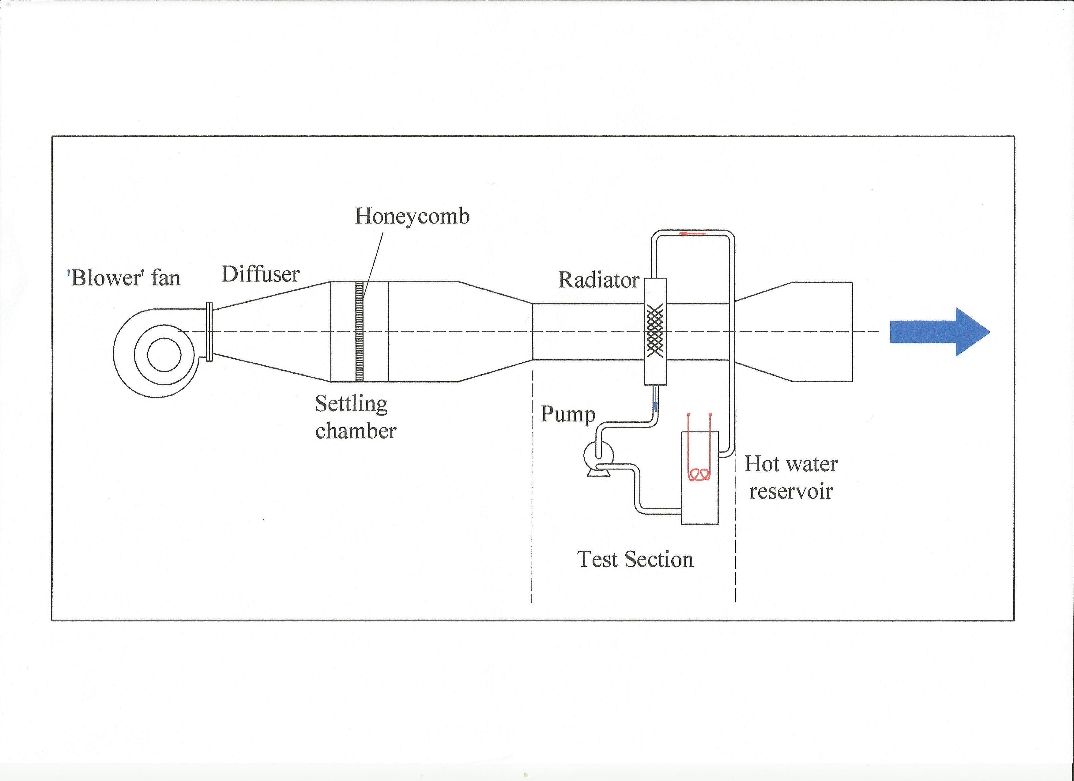 Fig. 1 - Radiator wind tunnel schematic
Written by John Coxon
8484