The DPX
 The most common type of engine dynamometer today used by engine builders the world over, must be the eddy current machine. But few will ever forget, of those who ever used them, the DPX water brake. Made by Froude in Worcester, England since shortly after the turn of the (20th) century, and once to be found gracing some out-of-the-way engine test facility at University, to many this would be their introduction to the subtle art of engine testing. Classed as a fluid friction device, resistance to the torque of the engine is offered by a combination of shaft bearing friction, friction in the sealing gland and the reaction due to the change in direction and momentum of a the water flowing through it.
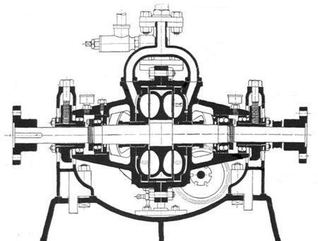
The dynamometer consists of a shaft carrying a rotor, which revolves inside a water-tight casing. In each face of the rotor there are a number of radial vanes set at an oblique angle to the axis of the rotor, the spaces between forming cups of semi-elliptical section. On each face of the casing and facing the others, is a similar arrangement forming another set of cups and while the rotor vanes face forward in the direction of rotation, these casing vanes are presented in the opposite direction.
With the rotor attached to the drive or output shaft of the engine, water at a constant input pressure (around 25 lbs/in2) is flung outwards by centrifugal force and thence into the cups in the casing. These cups serve as a guide to return the water to the inner part of the rotor where it is flung out again to repeat the cycle once more. The resistance caused by the action of the water between the rotor and its casing reacts against the casing which tries to turn on the trunnion bearings on which it is supported. Counteracted by a damped load arm, weights and a spring balance are used to measure the engine output torque. When taking any reading it was essential therefore that the load arm was precisely horizontal and aligned with a datum point on the machine for that purpose. This was achieved by operating a system of sluice gates using a hand wheel. These sluice gates when moved in or out, exposed more of the vanes to the water which either increased or decreased the resistance torque offered. The energy comprising the engine power output was converted into heat, which was dissipated by passing it through a cooling tower before being returned to the dyno.
Dyno testing back then was a question of manually balancing the output torque of the engine from within the engine test cell by adding or taking off balance weights and or using the dyno hand wheels to bring the load arm back to the datum. Often a spare nut or washer could be placed on the load arm to increase or decrease the 'power' the engine was giving to suit your purpose but that is altogether a different story!
Working from within the test cell things may have been noisy, it may have been very hot and certainly you were always aware of any strange noises coming from the engine, but by jolly it kept you well fit!
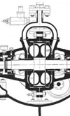
Fig. 1 - Cross-section of a Froude DPX dynamometer.
Written by John Coxon
5184