The ‘electric flywheel’
It seems that there is no middle ground as far as hybrid systems are concerned. They are applied to some of the world’s most mundane passenger cars, where the drivers are so careful in their driving habits that they are unlikely to reap maximum benefit, and they are a must-have in some of the more exotic race cars. Formula One, Le Mans, ALMS, LMES, WEC and JGTC have all taken advantage of the benefits of hybrid technology.
In terms of the exact technologies applied to racing hybrid systems, however, there is a middle ground. In one corner, we have electric hybrid systems, of the type used on existing production hybrid passenger cars. In such a system, current generated by a motor under braking is used to charge a battery which, when discharged, flows current back through the motor, generating torque and adding to the performance of the powertrain. In the other corner there are mechanical systems, where energy ‘harvested’ under braking is stored as kinetic energy in a flywheel. Flywheel energy storage is not new, but flywheel hybrids have not yet reached production in passenger cars, although according to various press reports its introduction cannot be far away.
Then there is a ‘middle way’ between the pure electric hybrid system and the pure mechanical systems, and this is the electro-mechanical (EM) hybrid, as raced by Porsche in selected GT events in recent years in a specially modified GT3 car, but with great success by Audi in endurance racing, collecting a very notable win at the Le Mans 24 Hours in 2012.
So, what is this middle way, and how does it work? The basis of the system is a flywheel, similar in appearance and concept to those used in mechanical hybrid systems. The difference is that the flywheel in the EM system is ‘loaded’ or ‘doped’ with magnetic particulates that can be magnetised in certain directions. What we have in effect is a large conventional electric motor rotor, although one in which the magnets are not continuous solids but are dispersed within a composite matrix. It is of higher inertia than a conventional magnetic rotor, but this part of the system does not act as a propulsion motor; it is merely an energy storage device, so its high inertia is an advantage.
The housing of the EM flywheel also contains a fairly conventional electric motor stator. The magnetically doped composite is a filament-wound glass fibre ‘ring’ which is shrouded with filament-wound carbon fibre composite. The carbon not only provides containment for the glass fibre, it ensures it remains in compression. It also provides a very useful degree of inertia. High-strength carbon is an ideal material for this owing to its strength. Conventional flywheel materials are not strong enough to prevent bursting at the speeds required to store sufficient energy.
Rather than using a mechanical continuously variable transmission as a way to transfer power, the EM system uses some fairly conventional power electronics to transfer energy between the propulsion motor (mounted somewhere in the driveline) and the EM flywheel. This means the energy storage and propulsion motor can be mounted remotely from each other. As shown in Fig. 1 here, the EM system ‘simply’ substitutes a conventional battery with an EM flywheel motor.
In selecting one of these systems for a race vehicle, the engineer needs to weigh the packaging advantages of each system, energy density, power density, longevity and reliability.
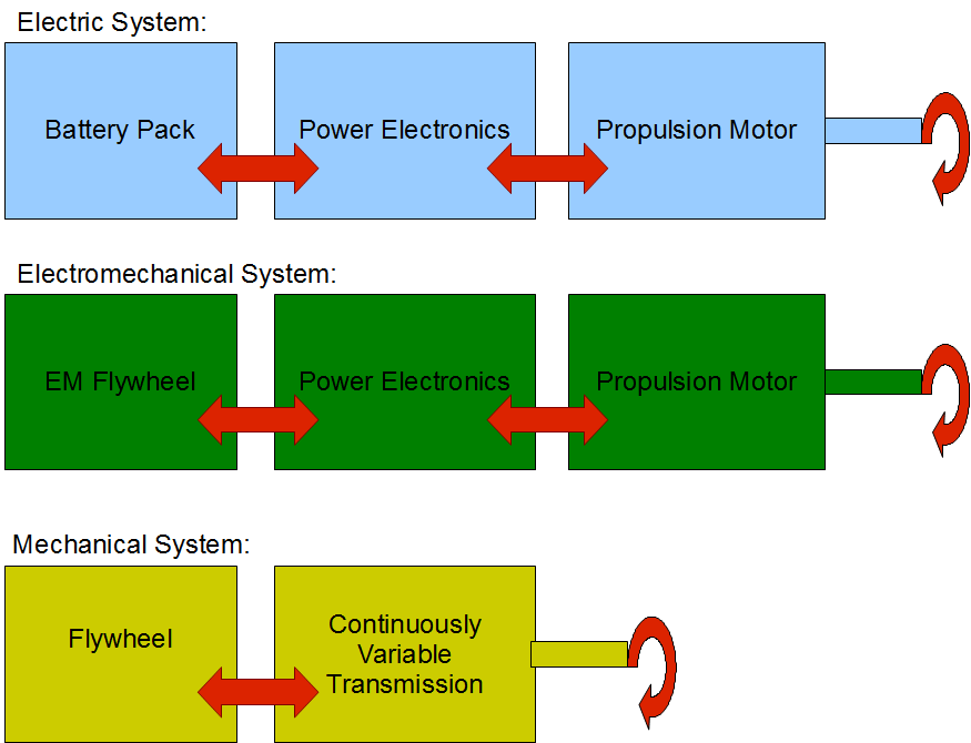
Fig. 1 - The basic architecture of the EM hybrid system compared to conventional electrical and mechanical systems
Written by Wayne Ward
3841