The end of the hose?
Next to the failure of vehicle electrics, leaks associated with the plumbing of the oil circuit were at one time the largest reason for a DNF (did not finish) on the motor racing scene. I well remember a time when vehicle under-bonnets were regularly streaked with oil and dirt, and much time was spent in the paddock between practice and the race, and again in the workshop at home, cleaning up afterwards.
These days though there are no excuses for oil leaks. There is an entire system of aircraft-quality hoses and hose ends available that can easily be assembled in the workshop and, when assembled correctly, not only do not leak, burst or come undone but are visually attractive and a credit to any vehicle engine bay. However, as with most things that are apparently simple, there is a lot more to this issue than meets the eye.
In any flexible hose connection there are generally two places where leakage can occur. The first is where the metal union connects to the component – for example pump, cooler or oil tank – while the second (and more difficult) place is that of the join between hose end and the hose itself.
The former is a simple matter of mechanical engineering design to ensure that the conical seat of the male part contacts the marginally differently angled conical cone of its mating part for all its 360º. So long as the clamp force is maintained, the joint should not leak. The connection between the hose and hose end is however a different matter, and depending on the diameter of the hose and the fluid pressure flowing through it, may require either a single nipple design or one using a nipple and cutter.
The single nipple design is, as you might expect, the simplest. With the female socket part of the hose end slipped over the braided hose, the male, threaded part of the hose end is inserted into the hose. When tightening the female socket, the hose gripped on its outside diameter by flutes in the inside of the female socket is compressed firmly into the space between female and male parts. Hence the wedge thus produced forms the one and only seal.
When pressures are greater or the degree of safety required is higher (as in the case of modern hydraulics, for instance – the nipple and cutter design is probably more appropriate, because as well as the single male nipple that fits tightly into the inside of the hose, a second nipple or cutter concentric with the first cuts into the hose elastomer material. During the assembly process the hose is grabbed by the flutes of the female socket, forcing the elastomer of the hose onto the nipple to create not one but two annular chambers [Fig. 1]. Should, for instance, the inner, primary seal leak, a secondary seal will prevent the fluid from leaking outwards – a sort of ‘belt and braces’ approach but one that is simple and, above all, reliable.
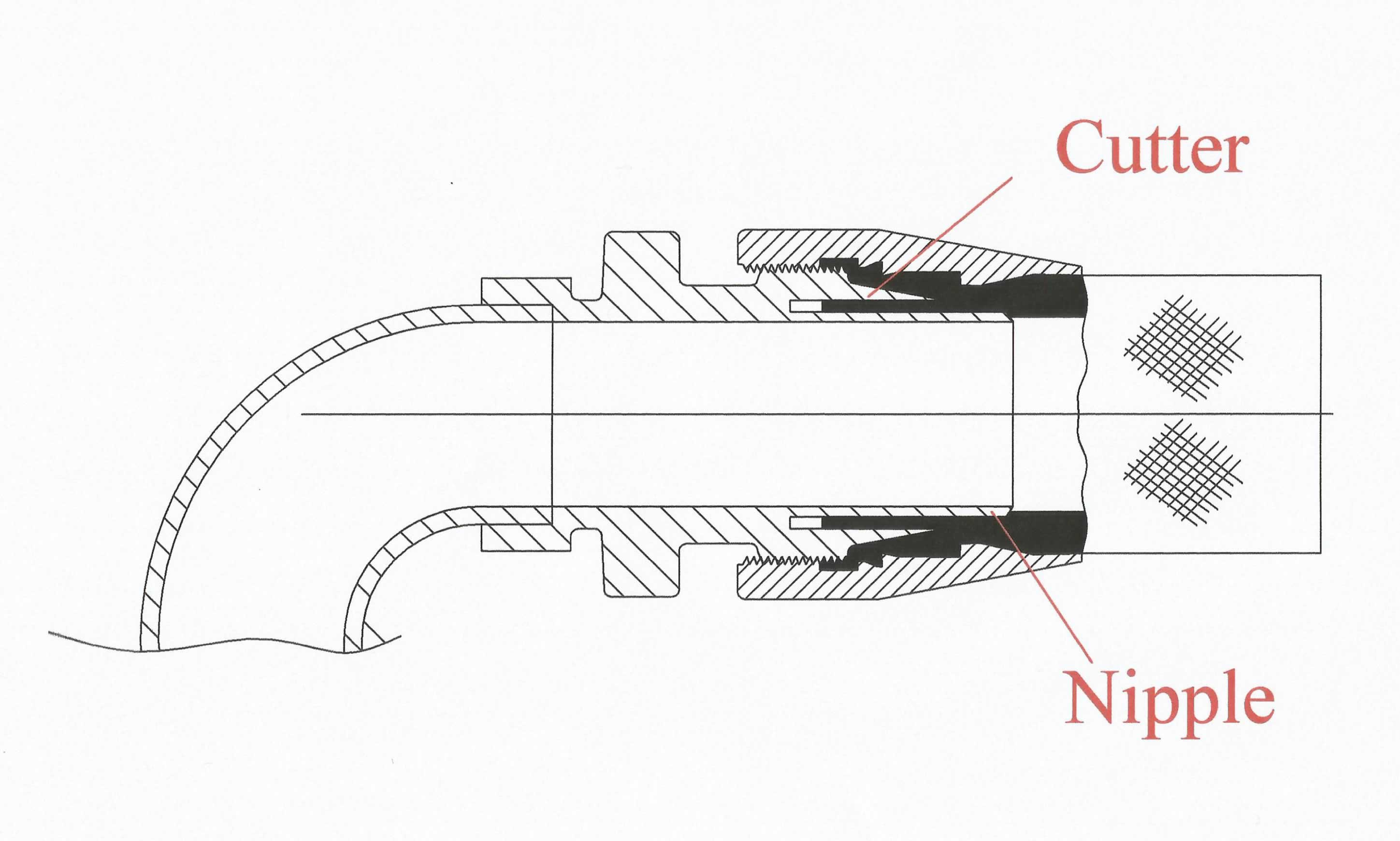 Fig. 1 - Nipple and cutter design
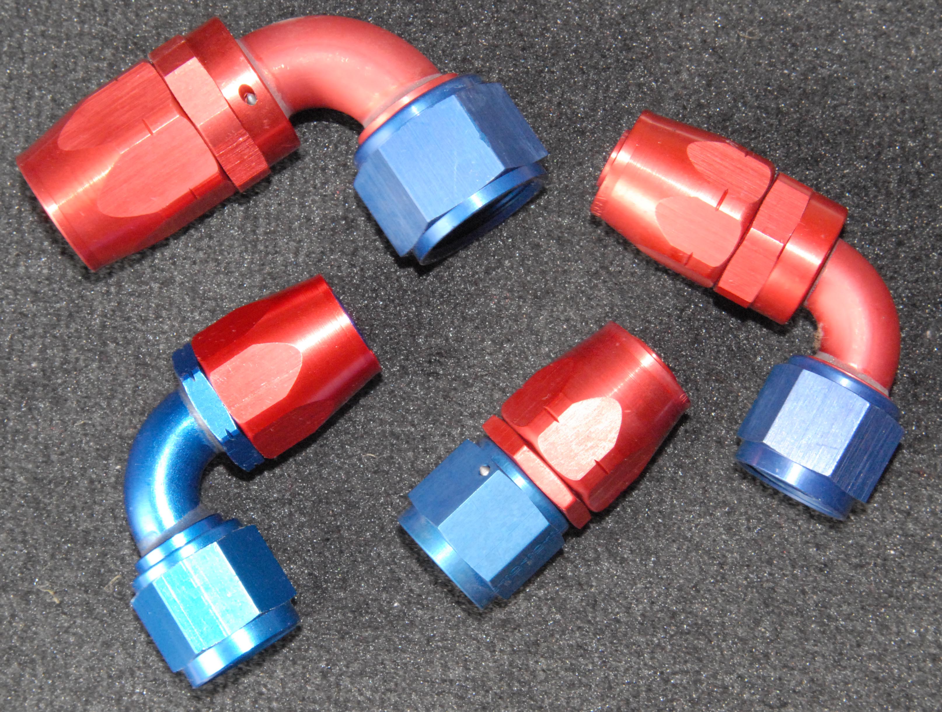 Fig. 2 - Selection of hose ends
Written by John Coxon
3698