The Fuel Rail
It seems strange to think that 30 years ago electronic fuel injection systems as we know and understand them now were really only in their infancy. Computers of course were really only for the ‘nerds’ in our midst, and anyway were generally too large, not sophisticated enough or too slow to handle the information needed to process them. If you can remember back that far, the carburettor was king, and some pretty sophisticated versions were available.
But the theory was simple. Take the fuel from the tank, pump it at high pressure (3 bar - we’re talking the 1980s here) to a common fuel rail and from there the injectors would direct it into the runners of the intake manifold. What could go wrong?
Well, plenty! The first thing was to ensure that for accurate injection volumes the fuel pressure had to be a constant value over the intake manifold pressure. The pressure relief valve recirculating much of the fuel back to the tank therefore had to be adjustable, with a pipe feeding the manifold air pressure signal back to the ‘other’ side of a spring-loaded bellows system. This was a mechanical solution to what was, in later years, achieved by a simple pressure sensor with a 0-5 V signal and, rather than altering the fuel pressure in the rail, the injector opening times were adjusted accordingly.
Designing the system to cope with both minimum and maximum fuel demand, the remaining issue was the fluctuation of the fuel pressure down the length of the rail. Repeatedly opening and closing the injectors along the fuel rail produces pressure fluctuations within it. Exacerbated by the heavily pulsated incoming flow created by some of the fuel pumps, these pressure pulsations could sometimes cause resonant effects which would alter the fuelling along the rail. Mysterious enough, but when trying to develop an intake manifold to give the best air distribution across the cylinders, this additional effect only served to confuse matters further.
In more refined applications, structure-borne noise was the issue which, happily, identified the source of our problem, the whole issue eventually solved using a fuel pressure damper. In a way, this was similar to the fuel pressure regulator having a spring-loaded diaphragm separating a fuel chamber and air chamber. At working pressure the fuel pressure regulator transfers all the excess fuel to the return line. Meanwhile the fuel pressure damper is so constructed as to maintain the fuel line pressure in response to a fuel pressure ’spike’, effectively altering the volume of the rail but only momentarily. Once this pressure ’spike’ has passed and has been attenuated in the process, the spring-loaded diaphragm moves back to its original position. This means the fuel rail volume is variable and not only accommodates the fuel when the pressure peaks occur but also releases fuel back into the system when the pressure drops.
Although generally not so much a problem now with more refined port-injected fuel systems, the high-pressure pulsations within direct injection designs are reintroducing this challenge to a new generation of engineers.
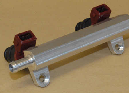
Fig. 1 - Aftermarket PFI fuel rail
Written by John Coxon
3804