The future
 Given current Formula One Kinetic Energy Recovery System (KERS) rules for Formula One, teams have found that the centre of gravity height and weight distribution penalty is less when employing batteries as the storage medium rather than a flywheel. Nevertheless, in future seasons, when the rules are modified so that the amount of energy that can be recovered is greater the required battery weight will increase disproportionately and it is likely that the balance will tip in favour of flywheels.
For now, the flywheel is the route Williams Formula One has chosen. It created its own KERS department by adopting a company set up by Ian Foley to pursue the technology. The result is now called Williams Hybrid Power and its brief extends beyond just supplying this technology to its parent company, but includes selling the technology both inside and outside motorsport. Likewise, Flybrid chose the flywheel solution for the package it set out to market within Formula One, but has now found enthusiasm from non-motorsport customers.

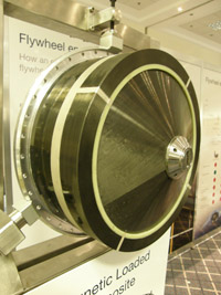
Both of these solutions rely on their flywheels spinning at extraordinarily high speeds to store the required energy in a sufficiently small and light package. Foley admits to somewhere between 50,000 and 100,000 rpm while Flybrid’s John Hilton is more open and reveals an operating maximum of 64,000 rpm. Unfortunately these high speeds generate an enormous amount of heat due to friction with the air and they both opt to run their flywheels in a near vacuum. This presents the problem of how do you get the energy in and out of the flywheel without venting air into the vacuum?Foley’s solution was to use a motor generator on the drivetrain as a means of creating electrical energy and then to convert that energy into the kinetic energy of flywheel rotation so as to store it. However, rather than have a second motor generator on the flywheel shaft, he turned the flywheel itself into a motor generator. The spinning wheel forms the rotor while the stator is part of the housing around it, which creates the partial vacuum. The wheel has been made from magnetically loaded composite that is wound from fibre embedded with magnetic particles. This allows it to interact with the stator as an electric motor rotor that can be spun up to speed, so as to convert the electrical energy fed to the stator into kinetic energy of rotation. To reverse the process, the spinning wheel can be made to induce a current in the stator to thereby retrieve the recovered energy and feed it back to the motor generator at the drivetrain as electrical current. Essentially the system is an electro-mechanical battery.

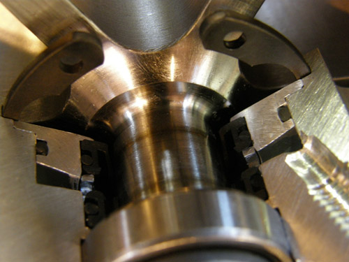
By contrast Flybrid did not wish to suffer the losses associated with creating and converting electrical energy and instead opted for a purely mechanical flywheel system whereby the flywheel shaft is connected to the drivetrain and consequently must pass out of the housing creating the partial vacuum. Having thus grasped the nettle of a mechanical link Flybrid dealt with the leakage problem by employing a particularly clever seal design. It has twin lips running on the shaft and the gap between the two is filled with oil at atmospheric pressure. Because there is no pressure difference between the oil and the atmosphere, no air is drawn in. There is, though, a huge pressure difference across the inner lip between the oil and the near total vacuum in the flywheel chamber. However, the oil molecules are much bigger than air molecules making it much harder to draw them past the lip than would have been possible with air. The result is very low leakage; just 2.0 cc in eight months of testing. Once inside the chamber, the oil is a special grade for use in vacuums that does not evaporate and can be cleaned out when the unit is serviced.