The sleeping beauty
 Can you imagine waking up one day and not remembering where you are? I'm only too certain that this may have happened to many of you after the recent festivities but the experience is probably something you would prefer to forget. Perhaps then you might spare a thought for the feelings of an engine upon being cranked into life. Waking from its enforced slumber the camshaft will tell it when to open and close the intake and exhaust valves but who tells it when to fire the charge and more importantly on which cycle?
In times past the ignition was triggered from a mechanical distributor, cleverly driven from the camshaft. For every two turns of the crankshaft, like the cams, the distributor rotated but once. Firing on cue for each cylinder in turn, the system was effective if somewhat inaccurate, even if it could be occasionally confused by owners setting it 360 crank degrees out. Importantly thought, it knew where it was at all times even when awoken from its slumber.
But then someone brought along electronics and eventually electronic engine management. While the distributor lasted a little while longer in the form of breakerless or transistorised ignition, it wasn't long before it was given its P60 and destined along with the carburettor to the scrap heaps of this world.
But the new system was full of promise and bright ideas and while it could pinpoint precisely where on a single crankshaft cycle it would fire the charge, of the two cycles it couldn't work out which one of the two especially after it had just woken up. On four cylinder engines this wasn't a big issue. Using a system called the 'wasted spark' system and a double-ended coil, two cylinders could be fired at once from the crankshaft at each rotation and while one spark ignited the charge, the other somewhat wastefully and harmlessly fired towards the end of the exhaust stroke on the other cylinder.
At this point riding to the rescue came the variable reluctance sensor. Used to measure the engine speed by supplying a series of electrical pulses, he offered to remove one of its teeth to indicate where he was on the engine cycle and then fitted to the camshaft, he would be able to indicate to the bright new thing where he was in the overall cycle. The problem here was that working from the camshaft, rather like the redundant distributor, chatter and backlash in the cam drive train could introduce inaccuracy and in any case he would only work while the engine was moving. All was rather sad and the poor bright new thing was very upset that he might never be able to demonstrate how good he really was…
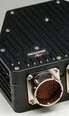
But then, suddenly and out of the blue came the Hall Effect Sensor! CKP, as he is known to his friends, needed a simple conducting (and therefore metal) toothed disc and together with his magnetic pickup could produce an electrical output with the passing of each tooth. And like the reluctance sensor, if he removed a tooth and was attached to the crankshaft he could tell where he was most of the time. Furthermore, unlike others, his output signal did not vary with engine speed giving the same waveform independent of how quickly he could move. This meant that the engine timing could be set whilst the engine was not running and pleased his masters so much that he was allowed a friend. With him looking at the crankshaft and his friend perched up near the cam between them the problem was solved and whenever the engine woke up in future it always knew where it was.
And they all lived happily ever after.
Fig. 1 - Hall effect sensor.
Written by John Coxon
3324