The thrust bearing
I think it’s fair to say that the crankshaft thrust bearing will not be very high on the list of priorities for most engine designers. And yet with higher engine output torques requiring greater (if somewhat intermittent) axial forces within the torque converter or clutch assembly, the thrust bearing now has to do so much more than it was originally designed for. And while a radial bearing can accept forces of many thousands of pounds per square inch, limitations of space and simple geometry ensure that at only a few hundred pounds per square inch, the thrust bearing may already be on its way to failure. The introduction of starting lock-out systems that require the clutch to be depressed before the engine can even crank only exacerbates the issue, and so, at a time when the lubrication is most critical (zero rotation, high load), there is little in the way of oil film present to support it.
Designed to control the end-to-end movement of the crankshaft to somewhere in the region of 0.004-0.006 in (0.1-0.15 mm) depending on the design, in small reciprocating engines thrust bearings take the form of either one-piece half-bearings incorporating integral flanges or loose separate semicircular, flat washers arranged either side of a central bearing. Prevented from turning in some way, and whereas the bearing journal relies on the difference between the journal diameter and radius of the bearing to create a ‘wedge’ of oil, the thrust bearing is limited by the fact that it is flat. That makes it much harder to create and maintain an oil film, so the only way oil can be introduced between it and the mating face of the crankshaft is by adding some kind of slight taper or including an oil groove directing oil spilling from the radial bearing.
Whichever way you choose, the loads able for support are far lower, making the manufacturing of both thrust bearing and crank that much more critical. In fact, because the two surfaces are flat – just like two metrology gauges when ‘wiped’ together – the tendency may be to stick. Thus if the axial load is so great as to displace the lubricating oil, causing the oil film to collapse, the surfaces could be inclined to stick together, overheat and then fail all the more readily.
While this may be an increasing trend given the increased axial loads, the only other way for the thrust bearing to fail is down to manufacturing or the (accidental, I assume) inclusion of dirt. Setting aside the most obvious concern of dirt, the difficulty in machining crankshaft thrust surfaces must not be underestimated either. Completed using the side of the grinding wheel during the same operation as the grinding of the journal, the surface not only has to be flat but also perpendicular to the axis of rotation of the crank.
The grinding wheel can also sometimes leave a swirl pattern of scratches, leaving a criss-cross pattern reminiscent of the honing patter in a cylinder bore. If not completely polished out, these can be highly effective in wiping away the oil film, and short-term failure will inevitably follow. So while the bearing design may be difficult, if the crankshaft thrust faces aren’t polished to perfection, all your efforts in engine build may come to nothing.
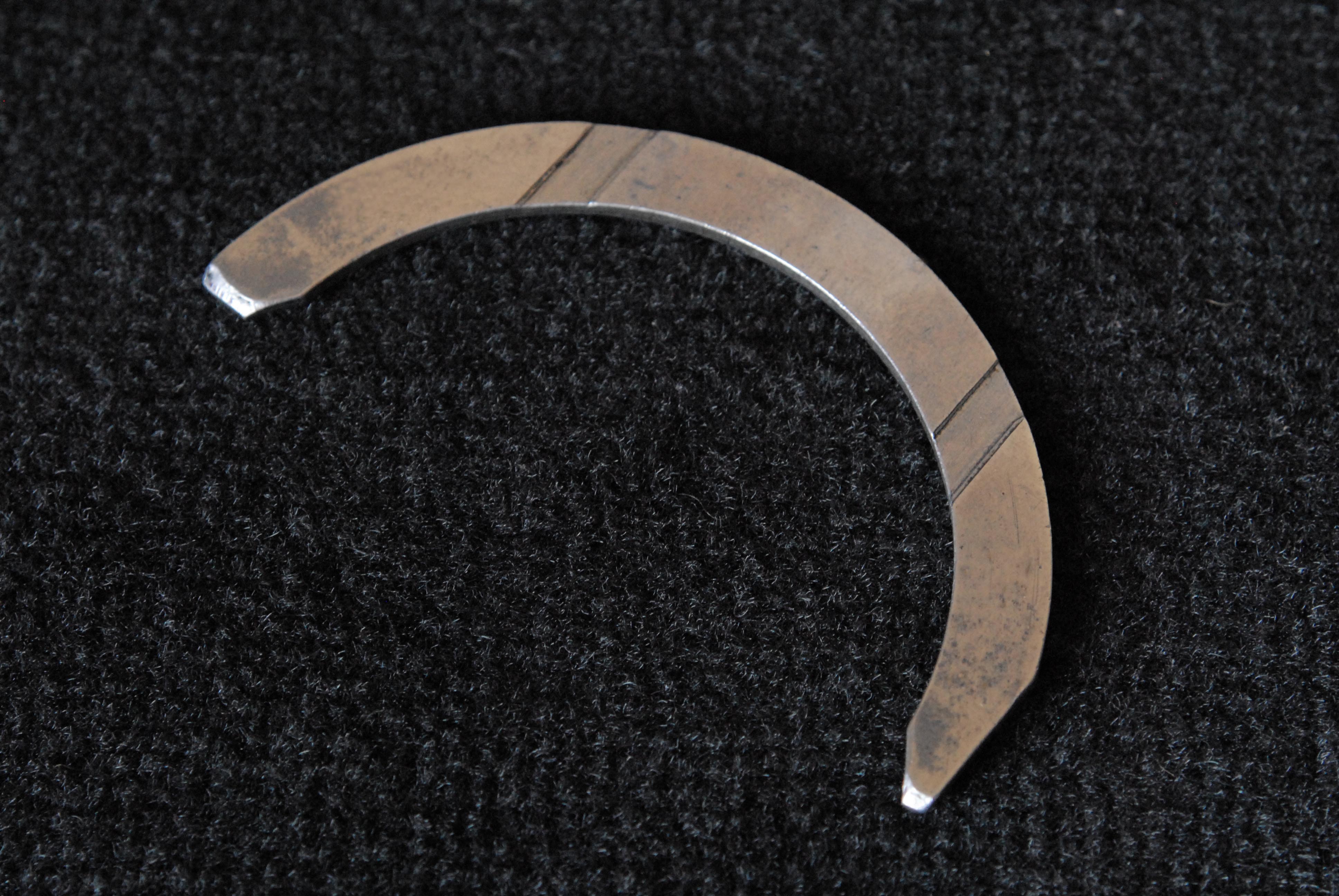 Fig. 1 - Semicircular crankshaft thrust bearing
Written by John Coxon
7572