The water brake
 The chassis dynamometer may be a convenient way of loading an engine, but to undertake any serious engine development requires a dynamometer attached directly to the output shaft of the engine. While there are various types of engine dynamometer on the market, perhaps the simplest and least costly is that of the water brake. Classed as a hydraulic machine, while some types of hydraulic dynamometer may use a pump to circulate oil, the water brake relies totally on a different fluid - water. This both resists engine torque and cools the dynamometer at the same time.
Essentially the device consists of a system of rotors and stators that transfer the working fluid (water) back and forth between them; the reaction thus created loads the engine. In controlling the flow of water on either the inlet side or outlet side - and sometimes both - using either manual or servo control, the amount of fluid passing through is adjusted to balance the forces and maintain the engine at the required speed.
Mounted on trunnion bearings at the front and rear, the resistance torque is measured by a simple linear load cell at the end of a beam attached to the casing of the machine. Generally designed to run in only one direction of rotation, simple machines of this type may have output flanges at each end to accommodate both clockwise- and anticlockwise-rotating engines.
Requiring only a steady supply of water (but greater than that normally found from a domestic supply) at a constant pressure of about 45-60 psi, dynamometers of this type are simple to install but will use large amounts of water if installed in a total loss system. For this reason, local water authorities may need to be contacted to ensure that there will be a sufficient supply of water, to ensure adequate control of the engine and also not denude any of the surrounding properties of their water pressure while you are testing.
In converting all the engine output power into heat energy, and assuming an upper limit on the outlet temperature of the dyno of about 60 C, the minimum supply of water should be of the order of 45 litres or 10 imperial gallons per minute per 100 bhp. Since water is a limiting resource in many parts of the world and possibly metered, the use of water brakes using total-loss systems may become progressively more expensive. For permanent installations therefore, the provision of a cooling tower to both cool and reduce the amount of water used should be considered.
Inexpensive to buy and install, the water brake does however have many disadvantages when compared to other dynamometer machines. While machines of this type may have low inertia and good speed control capability (often quoted as +/-5 rpm), adequate control of the load is generally considered to be poor. For this reason water brakes are not often used when dynamic test cycles need to be undertaken. Useful for engine break-in and general development work, water brakes may be ancient technology but still have a place in the world of modern motorsport.
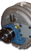
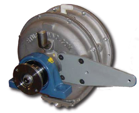
Fig. 1 - Typical modern water brake
Written by John Coxon
8200