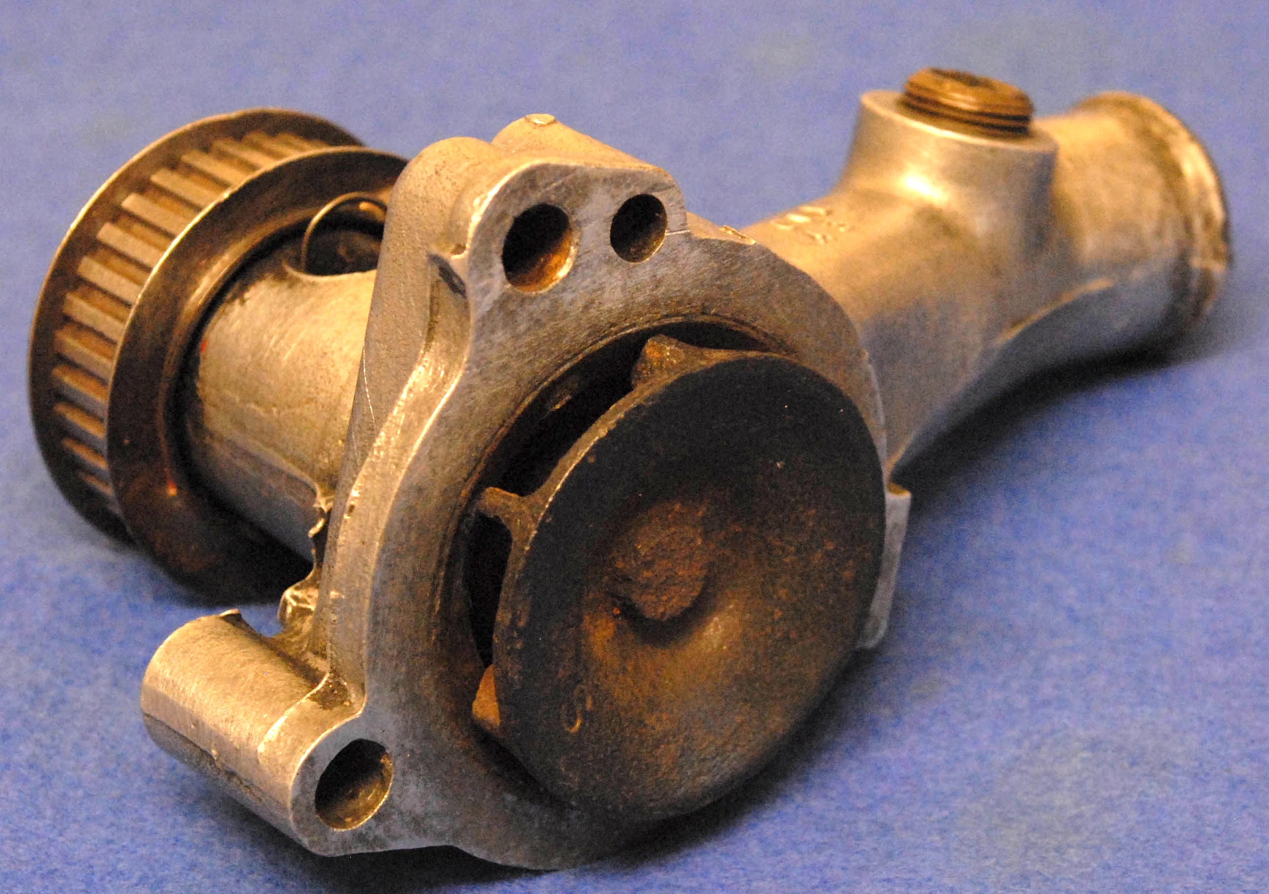
The water pump
It is a sad indictment of the spark-ignition engine that, even in its most efficient form, for every horsepower or kilowatt generated, the thermal equivalent of at least two more are lost as heat. And although up to half of this can be conveniently discharged directly into the atmosphere in the form of exhaust gas, the remaining heat – the amount roughly equivalent to the power output of the engine itself– has to be disposed of in other, less convenient ways. As my old thermodynamics lecturer used to insist on telling me, “For a 200 bhp engine, that means 150 kW or so of rejected heat to coolant, or 50 three-bar electric fires.” To ensure that no catastrophic damage can take place due to overheating, it is imperative therefore that this heat is taken away quickly and harmlessly – and the most efficient way of doing that is by using a liquid-based heat transfer system with a pump at its heart.
In the world of pumping there are many differing methods. Positive displacement pumps, for instance, can be used for low flow rates and pressures. For the highest flow rates and low-ish pressures though, axial flow pumps are often the preferred option. However, for medium flow rates having to work against high pressure ‘heads’ – as for example that created by the presence of a vehicle radiator – the only serious option is that of a centrifugal flow pump.
Reminiscent of a turbocharger’s compressor, the principle behind a centrifugal pump is much the same – flow is introduced into the centre of a spinning wheel (the impeller) and centrifuged out, thus increasing its velocity as it flows outwards. Guided by the vanes in the impeller, the additional velocity energy imparted to the fluid can subsequently be converted into pressure energy by the action of the diffuser in the outlet of the pump, and so while these pumps may not be the most efficient around (roughly 80% could be the maximum of a well-designed pump) simplicity rather than efficiency is usually the name of the game here.
In converting this velocity energy into pressure energy, care has be to taken to ensure that the diverging, conical section of the diffuser does not cause the formation of flow eddies at the wall and introduce undesirable losses in this portion of the pump. For some impeller designs, simple radial vanes might be the approach, whereas for other, more efficient types, backward-swept vanes may impart a much higher efficiency, though produced perhaps within a much restricted performance ‘window.’
In general, for forward-angled blades at the periphery of the impeller, the pressure head of the pump will increase with increasing flow rate, whereas if the impeller blades are swept backwards, more efficient pumping may be attained. In designs like this when the blades are swept backwards, the pressure ‘head’ achieved by the pump will most likely fall as the flow rate rises. This is quite the opposite to those facing forwards to the direction of travel which, as a rule, will increase the pressure head as the flow increases.
Using computation fluid dynamic studies, the complex behaviour of the engine coolant into and through the pump during operation is now being more fully understood, but somehow, although we may have more powerful tools, the exacting nature of modern engine requirements doesn’t seem to make the challenge of pump design any easier.
 Fig. 1 - Classic radial impeller water pump design
Written by John Coxon