The wiring loom
Providing power and signal cabling to every extremity of the car is the job of the wiring loom. But as the need for ever-tighter packaging in a Formula One car contradicts the spiralling complexity of the electronics, so the wiring loom has an ever-tougher brief to meet.
Connecting up the FIA-spec ECU and power box to all the electronic subsystems, sensors and actuators around the car, means the loom literally extends to every corner of the car. Although most of the major electronic boxes are mounted in the sidepods and the cockpit, the loom also needs to be routed around the powertrain, reach as far as inside each suspension corner, pass inside the front wing itself and climb upwards into the rear wing. The loom even has to be pass up inside the steering column to reach the steering wheel, complete with all its switches and rotary controls.
The cabling system itself tends to be fairly uniform across the grid, in either 55A or the lighter/stronger 55M wire specification. This is a silver-plated copper wire meeting the MIL-W-22759 and MIL-C-27500 standards. For a more flexible loom the individual cables are contra-wound, then sheathed in DR25 sleeves. Where the loom ends in a connector, a heatshrink boot is fitted; this is preferred over the MilSpec screw thread, which is rarely used in Formula One.
As connectors are to be covered in future F1-Monitor article, we will not go into details here, but the wire will be stripped and crimped into the connector blades, as soldering is a less consistent method.
To ease the mechanics’ task, the loom is separated into several subsections to allow the car to be rapidly disassembled. Thus one large central loom is installed in the monocoque, and this will be connected to smaller sub-looms for the engine, gearbox and each suspension upright. Other looms will be used for other removable or inaccessible areas, such as the fuel tank or the front/rear crash structures.
With so much cabling, the looms’ design needs to focus on size, weight and reliability. Gone are the days when the car chassis was finished and cabling would be retrofitted wherever space could be found; now the loom itself will be designed in 3D CAD along with the rest of the car. Every sensor, actuator and electronic box will be positioned on the CAD model to allow the loom designer to plan for every cable, taking into account space for bends, supporting structures and connectors. Sufficiently large apertures need to designed into the monocoque at an early stage to allow the loom to pass through.
Bespoke carbon fibre cable guides and junction boxes are made to ensure the loom is supported throughout its length. Owing to the heat around many parts of the car, the loom needs careful routing, and where diversion is not possible then sheathing with heat-reflective sleeving is used instead.
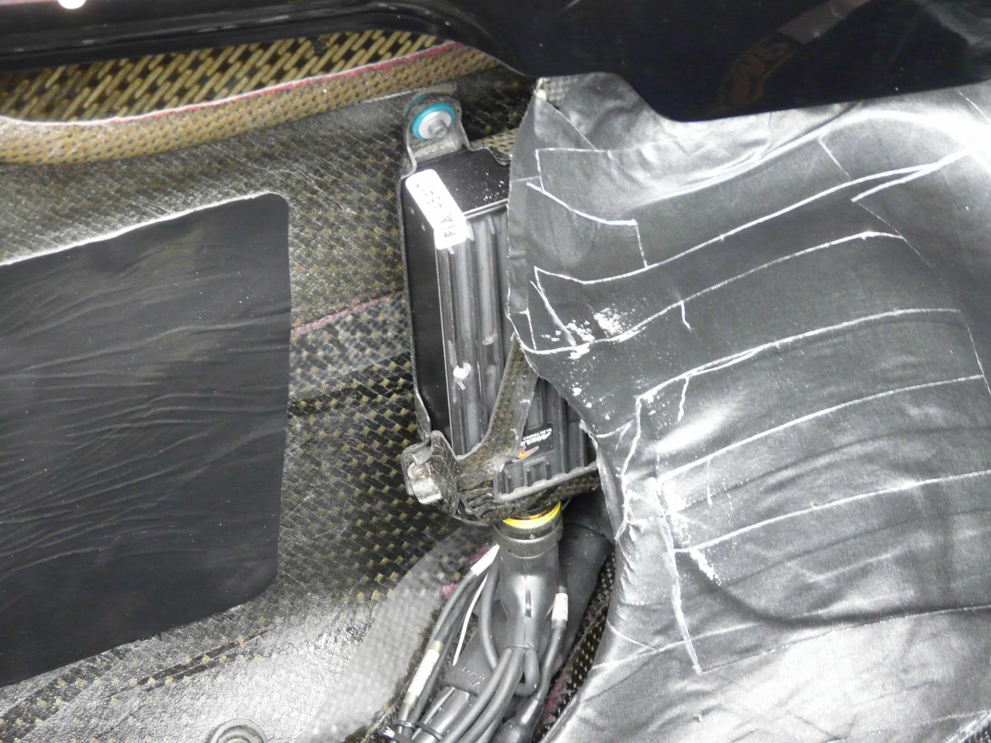 Fig. 1 - Every black box and its associated wiring is positioned in the master 3D CAD model at an early stage (Photo: Craig Scarborough)
Written by Craig Scarborough
3661