Turbocharger control
The operating range of a turbocharger is limited by the design of not just the centrifugal compressor but also that of the inward radial flow turbine which powers it. For the unit to work satisfactorily in service, the compressor wheel and casing on the engine air intake side have to be matched as precisely as possible to the exhaust gas-swallowing requirements of the turbine wheel and housing to ensure not only that the overall engine performance targets are met but also that both engine and turbocharger work within their safe working boundaries.
In the bigger diesel engines, which can tolerate large amounts of excess air, if matched correctly, no further control systems may be necessary. In smaller engines however, particularly spark ignition units, additional controls may have to be introduced. In this latter group therefore, turbocharger controls are a necessity, and fall into two categories – those that protect the turbocharger by limiting its speed, and those that protect the engine by restricting the compressor outlet pressure and hence the engine boost. Transferring all this a typical compressor map the operating envelope is therefore the compressor ‘surge’ line to the left of a typical compressor map, the maximum safe wheel speed to the top, and the compressor ‘choke’ area to the right.
For reasons of reliability and durability, it is always preferable to restrict turbocharger controls to the cold, engine air intake side of the application, if at all possible.
Perhaps the most obvious control is some form of blow-off valve. This is designed to re-route the compressor outlet air before it enters the intake manifold, and in most applications limits surge forces in the compressor wheel and bearing assembly when the throttle is snapped shut, as in the case of a gear change, for instance. Under such transitory conditions, interruption to the airflow would otherwise result in high-pressure spikes upstream of the throttle. A safety feature perhaps, but any bleed-off of the post-compressor air is wasted work by the turbine applying a back-pressure on the engine to compress the engine intake air in the first place, and therefore inefficient.
For maximum effectiveness and to increase overall engine efficiency, the boost condition is best controlled by limiting the hot, exhaust gas passing through the turbine wheel. The most common of these methods uses a wastegate or bypass valve, and takes its signal to open (limiting the flow of exhaust gas to the turbine), from a pressure tapping located on the compressor or a similar tapping from the exhaust manifold.
More usually these days, this bypass valve is integrated into the turbine housing next to the turbine wheel. These valves must be large enough to flow all of the anticipated bleed-off gas to prevent a phenomenon known as ‘boost creep’, which is the condition when exhaust gas flow completely overwhelms the bypass valve when fully open and the exhaust gas pressure consequently continues to rise in the upstream (exhaust) manifold. Under such conditions the intake manifold pressure will also continue to rise, creating even more exhaust gas and eventually producing dangerously high boost pressures with potentially catastrophic results for the engine.
From an efficiency viewpoint, however, the optimal method of controlling boost pressure is by using a variable geometry turbine. Sometimes also referred to as a variable area turbine nozzle, the most common of these consist of a circular array of pivoted aerofoil blades situated inside the turbine housing where the exhaust gas enters the turbine wheel. Designed to alter the angle of exhaust gas flow to the wheel according to its rotational speed, turbines such as these give much better low-speed torque characteristics as well as shorter spool-up times. As ever though, challenges to be overcome are the extremely hostile environment of high temperature gradients in the area and the corrosive nature of the exhaust gas.
With the increasing emphasis on fuel economy, not only in the auto industry but also the race track, surely it can’t be long until all engines – however small – are fitted with boost-controlled turbochargers.
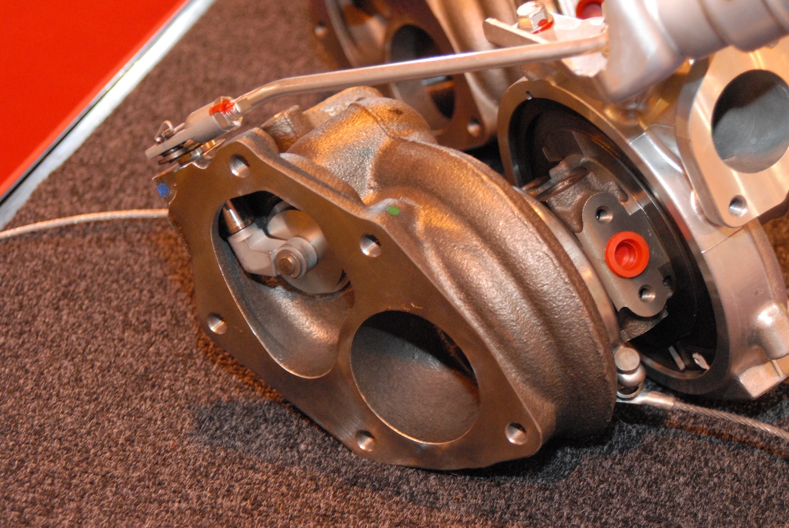 Fig. 1 - Turbo wastegate valve
Written by John Coxon
5752