Valve seat resurfacing
 Ever since the dawn of mass manufacturing, engineers have been preoccupied with shape and position but it is only in comparatively recent times that this has been formalised into a geometrical standard. The language of geometric dimensioning and tolerancing, GD&T to you and me, consisting of rules, symbols and conventions, was designed to ensure parts could be made anywhere in the world and put together with the highest confidence to produce a fully functional product or assembly. Specifying characteristics like form, orientation and location, one of the most frequent symbols seen on any engineering drawing, especially in the case of circular dimensions, is that of concentricity.
Take for example, the instance of a poppet valve, its guide and seat. If the seat is not concentric to the guide bore, every time the valve closes a bending load on the valve stem will be created. This will eventually fatigue the valve and its head will break off. And so while everyone is looking at the valve, the real culprit could be that of the concentricity between the guide and seat.
During initial manufacture, the locating bore for the guide and that for the seat insert will most likely be machined off the same centre. When this is the case the concentricity of the guide hole and that for the valve seat insert should not be an issue. However variations in the concentricity between the outer diameter and inner diameter of the guide and the way it is assembled in the head as well as those associated with the valve seat insert, will no doubt, introduce a level of uncertainty, between the bore of the valve guide and that of the seat when the whole lot is assembled. And unless the strictest of geometrical limits have been used, the alignment of the valve seat on the insert and the bore of the valve guide will have suffered to some degree. To correct this, it is normal to finish machine the valve seat using the bore of the valve guide as a datum.
One way, is to individually 'clock' each valve guide bore to the concentricity of the cutter spindle. Machining the valve seat thereafter will produce a high degree of concentricity. Potentially the most accurate method of all, the concentricity here is down to the skill of the operator, but with multi-valve heads this is surely only rarely practical. However most people, especially those in the re-manufacturing business, prefer to use other, much quicker means.
When it comes to re-machining valve seats there are basically two schools of thought and both of these surround the method of identifying the machining 'centre'. The first of these is sometimes called a 'live' pilot and fixed to the machine spindle but floating in the valve guide, the tooling cuts the valve seat while spinning in the valve guide bore. The other way and that patented by machine tool manufacturer, Rottler Manufacturing of Washington USA, is to use what is known as a 'fixed' or dead pilot which, it is claimed gives a greater degree of accuracy over the 'live' equivalent. Essentially this system allows a tungsten carbide centralizing stem to locate in the guide bore but, importantly remain stationary while the valve seat is re-cut. Because the pilot is stationary, the clearance between the centralising stem can be less than that of the 'live' pilot such that the concentricity between the valve seat and the guide can be as low as 0.01mm (0.0004in).
But accuracy invariably costs and at this level, speeds will probably be around 10% or so slower than the 'live' pilot. But in the search for perfection surely this is of little concern?
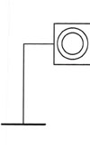
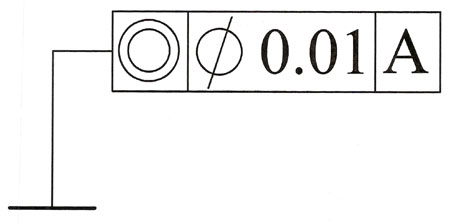
Fig. 1 - Internationally recognised symbol for concentricity along with the limits allowed with respect to datum A on the drawing
Written by John Coxon
3801