Wiring connectors – past and present
I can’t think of anything more annoying than those little intermittent electrical faults. You know the type, the ones that cut the engine out halfway around the first lap of practice and then mysteriously disappear when you get the car back to the pit lane afterwards. At this point the older hands among us resign ourselves to a long day ahead.
With modern diagnostics systems, problems with engine management, wiring or sensors are generally easy to diagnose, even when they’re intermittent. However, when the vehicle involved is somewhat elderly then the issue is almost invariably electrical, with the diagnosis remaining slightly more challenging. The particular case I am talking about above was thought at the time to be down to either a broken wire somewhere in the loom, which was not immediately obvious, or more likely a loose or ill-fitting terminal. And when you consider that the vehicle was fitted with a number of 1960s-type spade terminals, those of us familiar with this machine knew just where to look.
The problem with spade-type terminals and others like it is that they are perfect cantilevers. By that I mean that supported at one end, the area with the highest bending moment, the other unsupported end will be free to vibrate. And mounted in a racing machine where the engine is bolted directly into the chassis, the resulting vibration can cause havoc. Attaching the female part of the connection simply makes matters worse because, as well as the uncertainty of the electrical contact between male and female parts, the added weight on the cantilever will create a bigger bending moment at the base of the male part. At the same time this will reduce its natural frequency – and, knowing my luck, just into the frequency band produced by a four-cylinder engine at a speed to create resonance! Once the bending stress at the base of the spade goes beyond its critical limit it won’t be long before the cyclic loading cracks the terminal, and then catastrophic failure follows.
It need not be like this though. All you have to do is look at modern sensor technology and apply a little logic. Modern automotive sensors – the type used to generate input and receive output signals to the engine ECU – no longer have single fixed bayonet-type terminals. Connections are generally made using moulded multi-pin plugs or, where that is not possible, the sensor will be fitted with a flying lead of some description [Fig. 1]. This flying lead will be bonded into the sensor at the critical end and attached to a moulded two-, three- or four-pin plug at the other. Mating with the opposite male or female part of the main wiring loom and clipping firmly together, the resulting connection will be durable and, if the appropriate sealing method is used, watertight. Simple, relatively cheap and above all reliable, especially if the connector is clipped away to a supporting panel somewhere out of harm’s way.
Oh, and in case you wanted to know, the car was repaired in five minutes and, starting last on the grid of 30 finishing a creditable 11th. If only it had been fitted with more modern connectors!
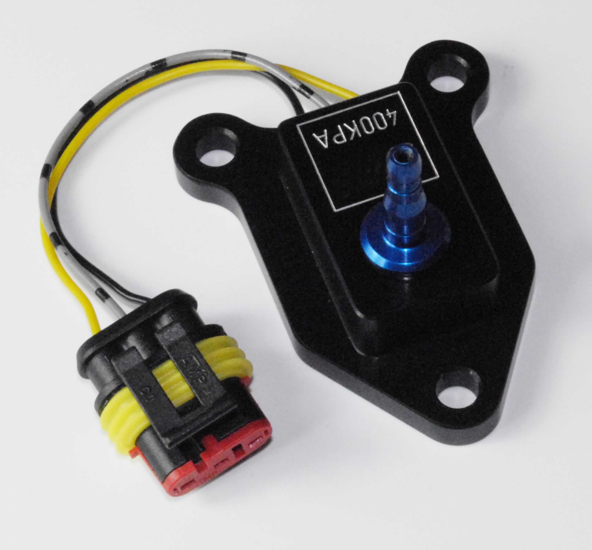 Fig. 1 - A flying lead sensor
Written by John Coxon
4965