X-by-wire
 One of the biggest changes to the engine ECU in recent years has been the rise of the drive-by-wire system. Generically known as 'x-by-wire' or sometimes (incorrectly) as 'fly-by-wire', such systems were introduced by vehicle OEMs in response to more punitive emissions legislation in recent years.
Consisting of a throttle pedal device requesting a torque demand from the engine, the engine ECU calculates the ignition and fuelling necessary and requests the appropriate amount of air from the engine throttle. With no physical cable connecting the throttle pedal to the unit on the engine, communication is achieved solely via electronics and digital signals. Systems similar to these were first used without mechanical back-up in the F-16 jet fighter in 1974 and then the Airbus A320 commercial airliner 14 years later.
While the complications associated with flight control make systems of this type ideal for large or sophisticated aircraft, for most motorsports applications drive-by-wire throttle systems are mainly an unnecessary complication. But with the increasing amount of 'spec' or crate engines derived directly from OE manufacturers, having electronic throttle bodies, aftermarket ECM suppliers are having to incorporate drive-by-wire routines of their own to keep pace with the market.
Having few technical advantages for most forms of motor sports, the lack of a direct mechanical link places a greater emphasis on the reliability of the data being processed to ensure that the signal given to the throttle is reliable 100% of the time. With a mechanical system this is guaranteed, but when independent electronic control is used without a mechanical back-up, the system has to have a certain degree of redundancy and, were it to fail at any time, to fail safe.
To minimise if not totally eliminate the concern, both the throttle demand pedal and that at the engine need two entirely independent monitoring systems. Consisting of separate throttle angle sensors - increasingly of the non-contacting (and therefore much more reliable) Hall-effect type - two are required for the throttle pedal and two on each of the engine throttles. For an inline engine, that amounts to four channels simply looking at the throttle position but for a vee engine, assuming only one throttle per bank, this rises to six!
Each sensor on the same spindle will be calibrated separately, such that when the throttle position is calculated its exact position can be identified with confidence. For example, one sensor might be calibrated on a 0.5-4.5 V scale, ascending when opening; the other might offer the same voltage but descending while opening. The two different methods should therefore come up with the same throttle angle.
Other options could be 0.5-4.5 V for the first sensor 1 and 0.5-2 V for the second. Either way though the two input voltages to the ECU will be able to pinpoint precisely the pedal demand requested and process the signal with a high level of confidence. Should these two differ in their expected output, the system will inevitable fall into a default or 'limp home' condition.
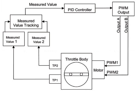
While this may seem complicated enough to the non-specialist it gets worse, much worse. To power the engine throttles opened and closed, the throttle body will receive two pulse width modulated signals - one to open the throttle valve, the other to power it closed. This will be undertaken using DC servo motors using a form of electronic PID (Proportional, Integrated and Derivative) feedback control. The significance of these is explained in this month's Dynamometer offering but with two circuits required for each throttle valve, already the complication is increasing.
Drive-by-wire may be the future of roadcar technology, and its usefulness in other systems such as traction control make it highly attractive in terms of general everyday road safety. But for the weekend racer in years to come it could introduce an awful lot of unnecessary grief.
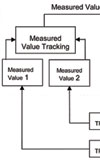
Fig. 1 - The drive-by-wire throttle circuit
Written by John Coxon
3811