You’ve never had it so good!
 I think it was British Prime Minister Harold Macmillan who is claimed to have first coined the phase, “You’ve never had it so good.” In a speech at a Conservative party rally the phrase referred to the fact that after 15 years of shortages and rationing, the post war economy was now looking rosy again. But for anyone involved in cam design the phrase may be as true in 2009 for him/her, as it was back in 1957 for the people of Britain.
Today, with powerful user-friendly computer software, kinematic cam profile analysis may be readily undertaken using ‘one click’ template driven models, manipulating profile lift data or derivative curves and produce almost instant on-screen designs. With the motion originating from either the cam or the valve end of the mechanism, this is now usually described in either many-segmented polynomials or in the more recent piecewise Bezier curves giving complete control over lift, velocity, acceleration and jerk data satisfying all the necessary boundary conditions.
But it wasn’t always like this. Indeed long before the advent of the computer, cam design was very much in the hands of the specialist who had limited means to analyse their designs let alone fully understand the implications to the valve train.
Most cam design methods start from the acceleration curve and express this against crank or cam angle in graphical form. Acceleration in the valve train is a function of the contact forces - at first resisting the lack of motion of the valve on the opening flank and then again slowing it down on the closing flank. In between, the zone referred to as the ‘nose’ of the cam is the area where the spring is coming into play and although these contact stresses increase with camshaft speed, it is the instantaneous radius of curvature of the cam producing the Hertzian stresses in the material, that creates the limitation here. However the quality of any design is also to a certain extent how smoothly the curves from each section blend into each other reducing ‘jerk’ and its potentially harmful effects.
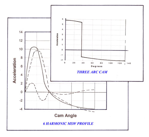
Early post World War 2 automotive cams were often based on so-called, ‘3 Arc’ designs. Relatively easy to draw and specify for manufacture, acceleration rates rose instantaneously from zero to a high value at the start of lift and then dropped away even more suddenly from positive to negative at the junction of the flank to the nose. Equivalent to a hammer blow, these high ‘jerk’ designs were only tolerated because of the low stiffness inherent in the valve train and the slow speed of the engines at the time. The two sine wave profile came next. Consisting of a positive sine wave acceleration curve followed by another, longer one of lower ‘negative lift’, designs of this type produced large cam lobes for a given lift, which restricted its use but did reduce spring surge. Further developments, introducing the idea of multi-sine waves (up to 6) or ‘harmonics’, enabled more suitable lift curves to be produced enabling spring forces to be reduced and better control of the jerk between the flank and nose.
Over the years these trigonometric designs made way for those relying on polynomial equations. Superior in many ways, they provided smoother action to the valves, producing less vibration, wear and noise, were easier to manufacture and required reduced torque to drive them. Satisfying the equation:
y = C0 + C1x + C2x2 + C3x3 + C4x5 + C5x5 + C6x6 + C7x7 + ……
and inserting the boundary conditions as well as those in the three derivative curves of velocity (dy/dx), acceleration (d2y/dx2) and jerk (d3y/dx3) and then substituting the values back in, eventually produced a series of polynomials for further analysis. At a time when electronic calculators speeded up the process only slowly and trigonometrical tables were de rigour it might take as much as a whole week or more of successive iterations and diligent endeavour to produce a profile at even one-degree intervals. Generally limited to the 6th power of x, by time alone, cam design was a long and time-consuming exercise.
That the overall engine design process has become more complicated, there is no doubt. But with modern software and the ability to produce highly efficient cam profiles with minimum jerk (maximum smoothness) between sections, the process of designing the cam profile itself is no longer the domain of the specialist.
Written by John Coxon.
4244