Back to basics
I would guess that very few of those who handle cams – in that they either buy them or install them, or have some form of interaction with them in any way – have ever thought about the actual profile of the cam and the way it is generated. Sure, enthusiasts regularly talk about cam timing and lift, or even about valve lash or ‘lobe separation’, but in consideration of how such timing and lift is achieved in the practical sense I’ll bet that only a tiny fraction of them will have ever wondered about the ‘profile’ and how it is generated. Which begs the question that, faced with the task of opening and closing these new-fangled poppet valves, how did early engineers design their camshaft profiles?
We know for instance that early power unit engineers understood, as far as they could at the time, the importance of valve timing. They knew for instance that, for best power, cams needed to be of long duration, while for driveability, shorter-duration cams were far better. Furthermore, for equal valve area and lifts, the inlet cam duration should be slightly shorter than for the exhaust cam. Clearly this is not always the case but it’s a good starting point. Thus in the case of the 7.6 litre four-valve Peugeot Grand Prix engine of 1913 the direct-acting inlet cam duration was 223° crank angle, while that of the exhaust was 248°. In developing such an engine, solid engineering principles will have been used together with fastidious experimentation, but in all of this nowhere is it recorded how the actual cam profile was developed.
From various company archives that still exist, pre-1930 camshaft profile data for manufacture tended to be recorded in terms of the radius of curvature of an arc and the centres around which this was based. This was as much for ease of manufacture as anything else. With an opening arc, a closing arc and the bit in between describing the radius of the ‘nose’ of the cam, these were described as ‘three arc’ cams, the arcs actually referring to the base circle, the flank and the nose. Comparatively easy to grind, the cams were designed such that the tappet velocities at the intersections were continuous, to produce a simple harmonic motion of the valve. Unfortunately, although the velocities were the same, this produced instantaneous changes in acceleration that would lead to extremely high levels of ‘jerk’ (the rate of change of acceleration), creating unwanted harmonics in the valvetrain and leading to valve surge or spring failure – or at the very least a noisy and inefficient valvetrain.
And while the three-arc cam had no ramps to lift the valve initially off its seat, the introduction of these into the profile led eventually to the five-arc cam, and so things developed. If valves were pushrod-operated, flexing of the pushrods (and therefore lost motion in the system) could result, but the effects of high rates of jerk along the rest of the valvetrain would be advantageously constrained in some way. Likewise, in some overhead cam designs the flexing of the rocker shaft could help protect the rest of the valve train. Luckily enough, most engines during this period were not particularly high-revving, the 1913 Peugeot revving to only about 3000 rpm, while 20 years later, Vittorio Jano’s 2.7 litre straight-eight Alfa went up to a little over 5600 rpm.
So if you’ve ever wondered why vintage and classic vehicles are so much more faster than they used to be, maybe it’s not just because of the tyres or of the newer and stronger engine materials used, maybe it’s because with improved valvetrain design methods brought about by a greater understanding of the valve train, the cam profiles now being ground are so much better.
Now I bet many of you didn’t think about that.
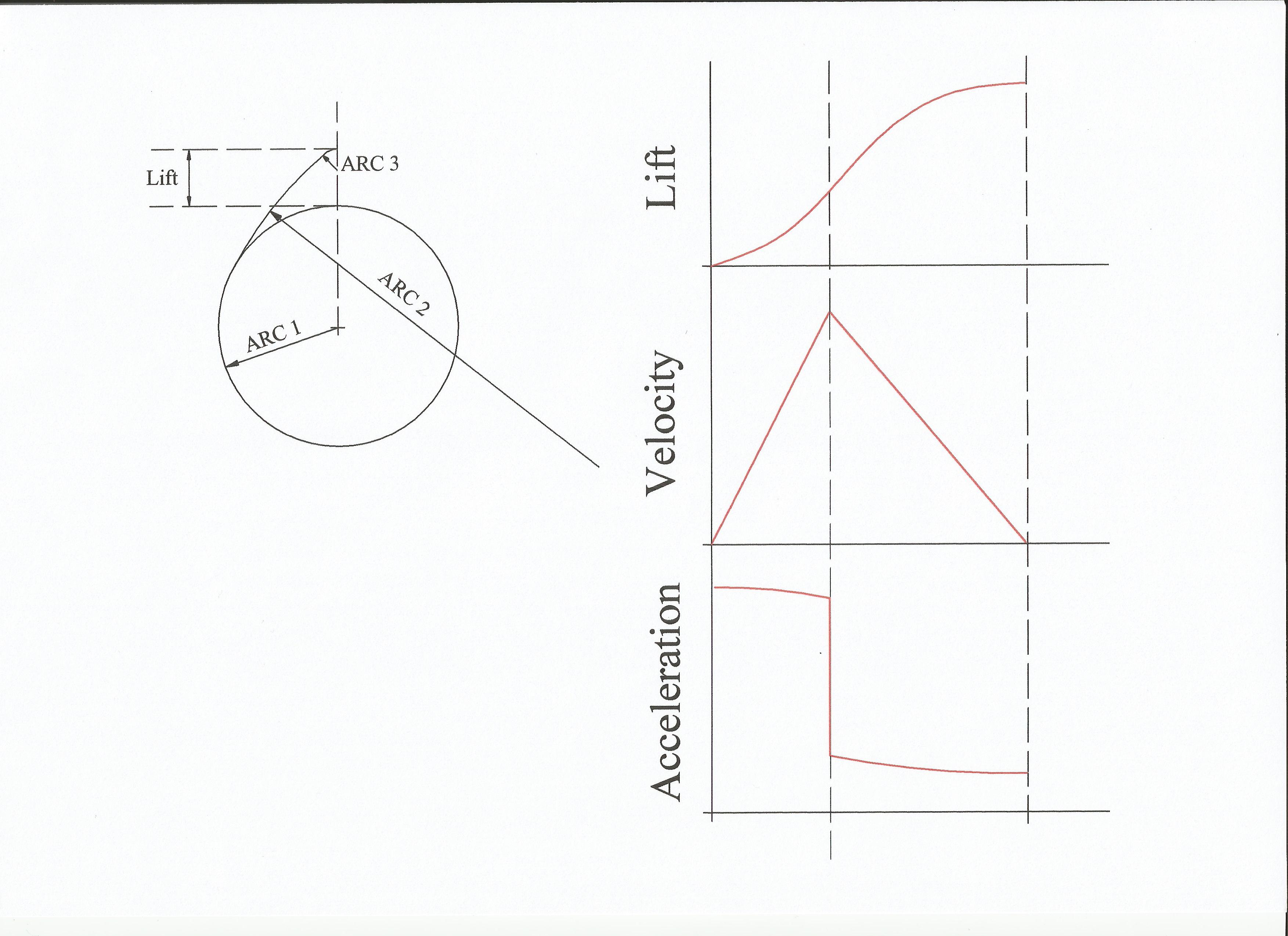 Fig. 1 - The three-arc camshaft lift, velocity and acceleration curves
Written by John Coxon