It’s all about timing
Much has already been written in these columns about the technicalities of cam design and manufacture. But unless the component is properly installed in the engine so that the intake and exhaust valves are accurately phased to the motion of the piston then much of the effort involved in designing the cam may be completely lost. Rather like a stand-up comedian, when it comes to speaking of camshafts, timing is everything.
For most applications I guess it is safest to suggest that, when installing an aftermarket camshaft into a production-based engine, follow the guidelines as issued by the cam supplier. These may request the engine builder to set the peak inlet valve lift to a certain number of crankshaft degrees after top dead centre (TDC), when the piston is at its highest in the bore. In some designs, while it is relatively straightforward to determine the piston TDC and therefore the number of degrees after it, because of the dwell period (when the cam remains fully open) this maximum lift approach is not particularly useful. In such cases it is better to plot the lift versus degree curve towards maximum lift, and the same again after the peak when the valve is closing again. In this way the average of the angles at the same lift will correspond to that of the peak.
In high compression ratio engines when valve-to-piston contact could occur, it might be wisest to assemble the valve using lighter valve springs to establish the valve-to-piston clearance around the inlet valve opening (and exhaust closing) and piston TDC. Using lighter valve springs and a dial gauge on the tappet, the valve can be pushed down to the point of contact at each degree through this critical zone. As well as minimising any potentially catastrophic valve-to-piston contact, this process will establish how much tolerance can be accepted in the timing before serious damage can take place. This is something I believe needs to be established quite early on in any build process should any cam timing optimisation work be contemplated at a later stage.
The timing method above of course assumes that the profile is fully symmetrical, and for many profiles this is still the case. However, in a growing number of engines where, for instance, roller rocker systems have been incorporated, cam lobes are not symmetrical. In cases such as this the cam grinder will no doubt have given you the cam timing at either 1 mm or 0.050 in lift on both the opening and closing flanks. Measuring the actual timing by turning the crank in the direction of rotation, and noting the crank degrees at both 1 mm (or 0.050 in) lift at the opening and closing side of the cam, and comparing them with that required, will soon move you in the right direction.
But assuming you have determined the actual timing as assembled and compared to that required by the cam grinder, invariably there will be a difference. To correct this we have a number of options.
The first and perhaps simplest of these is to use a fully adjustable vernier device. Rotated to the amount necessary and then securely clamped, this is quick and easily understood, taxing the brain as little as possible. However, these vernier devices have been known to slip and are comparatively bulky, so a lot of builders still prefer to use other methods. The other options of ‘offset keyways’ or multi-hole timing wheels are, in my opinion, more robust, lighter, above all cheaper but may require mental dexterity to fit the correct amount of offset or align the correct holes to give the timing required. Once set though, the timing is unlikely to change – unless something else has gone drastically wrong!
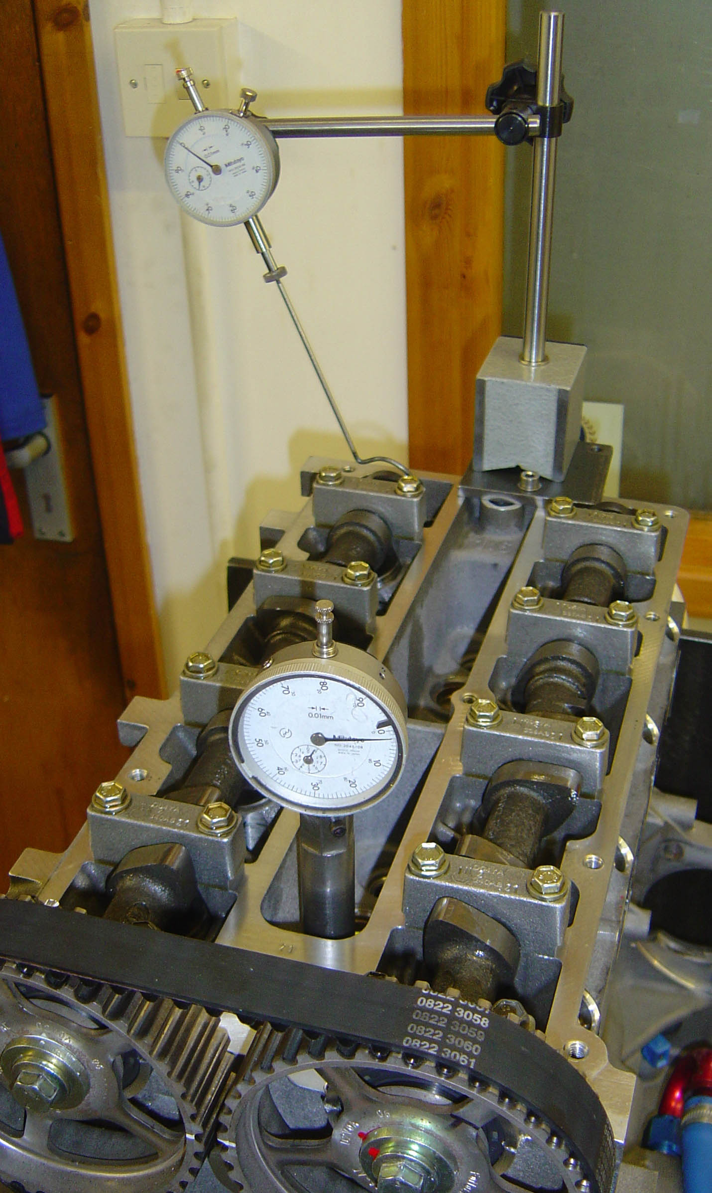 Fig. 1 - Timing a Formula Ford 1600 engine
Written by John Coxon