Split cams
 A few months ago, in May I believe, we looked at a variable duration cam made in two pieces. While this was a novel approach to optimising the airflow into an engine over a range of conditions, reader Reine Gustafson of AGAP in Sweden contacted me recently about another cam design idea. This too consists of more than one piece and, as you will see, is simplicity itself.
Now there can't be a cam designer or engine builder who hasn't been confronted with this problem at times and
who hasn't wanted a higher lift profile than the one in his possession. The problem, as I am sure you have been quick to realise, is that in certain types of engines - particularly those of an older type, with the camshaft mounted within the cylinder block structure - installation has to be made through the end of the block. The cam bearings have to be carefully oiled and the whole camshaft judiciously pushed through successive bearings before being secured against some form of thrust plate.
The problem is that the circle prescribed by the rotation of the cam lobe has to be less than the diameter of the supporting bearings in order for the cam to pass through. While this is rarely an issue on many types of road-going older engines, when it comes to designing higher lift cams the options are somewhat limited.
On overhead cam engines we get around this problem by using separate cam upper bearing caps, and the constraints on the cam lobe design suffer one less restriction. But when the cam is mounted in the block the only option is to go for a smaller base circle, if possible, or extend the duration of lift to give a less pointy cam nose.
The former will inevitably increase the level of contact stresses while the latter may give far from ideal gas dynamics. Either way, there are compromises to the design, which can be removed after a little thought.
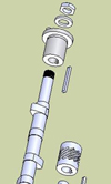
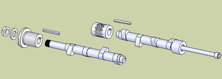
The solution, according to Mr Gustafson, is to manufacture the camshaft in two halves with a separate centre bearing. Manoeuvring each half, front or back into position via the sump and between bearings, central support is offered by a separate bearing inserted just prior to the installation of the second half. Using a keyway to locate all three radially, the system is locked using a single long bolt down the centre. A quick look at the accompanying pictures will explain all. Currently patent pending, the design allows much higher cam lifts than would otherwise be possible.
The design was prototyped on a vintage Model A Ford used for a Hot Rod, and from a standard valve lift of 7.67 mm, a further 5 mm could just about be introduced before other issues crept in. An innovative solution to a common problem on older engines, for higher powers the designer says that a more elegant solution, replacing the keyway with splines, could be incorporated.
It's a simple and neat solution to the problem, but now the task is to make sure the rest of the engine can cope with the increased performance.
Fig. 1 - Exploded diagram of the centrally split cam
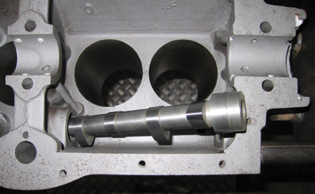
Fig. 2 - Manoeuvring the rear half into position.
Written by John Coxon
5877