The domed tappet
 For anyone starting out on a clean-sheet engine design it is always worth remembering the notice at the entrance to the Sahara desert. The notice, or so I am reliably informed, says something like, "Choose your rut very carefully…. you will be in it for the next 500 miles!" And for those who have had the good fortune to design a totally new engine, such a warning can never be taken too lightly, because design decisions made in the early stages can often bite back on you much later in the process or even years down the road.
Take, for instance, the selection of valve sizes and their ultimate effect on the lift of the camshaft. The theory goes that, for a race engine, the intake and exhaust valves should be of a suitable diameter commensurate with that of the cylinder bore and hence displacement of the engine. Thus, for a given size of engine, the valve diameters and therefore valve spacing will be set at an early stage in the overall process.
Now, assuming we have opted for the comparative simplicity of a direct-acting overhead camshaft with parallel valves, the selection of the valve diameters has by default essentially dictated the diameter of the inverted direct-acting buckets most commonly used in such applications. So we have indirectly, either willingly or unwillingly, limited the maximum valve lift velocity available from the camshaft. For a given duration of opening, this will ultimately limit the maximum lift of the valve.
At this point, many might try to illustrate the situation by using the complex mathematical formulae involved in camshaft design; however, I prefer to imagine the side-on view of the camshaft as it rotates across the follower. When the valve lift velocity is low, the flank of the cam has more curvature, and the point of contact with the tappet moves slowly across its top face.
As the curvature of the cam becomes less pronounced, the cam becomes more 'aggressive' - or more 'intensive', as some prefer to call it - and therefore moves much faster across the bucket face for every degree of rotation. The maximum velocity achievable therefore depends solely on the diameter of the tappet.
When the designer is up against it and needs that last little bit of valve lift, the contact point can move out beyond the edge of the tappet, but this will invariably cause the edge of the bucket to 'dig in' or at least cause lubrication issues. Some cam designers surmount the problem by introducing a tiny amount of curvature to the bucket face. In the past this may have been done to encourage the valve to spin using a slight taper on the lobe to give eccentric contact, but these days truly flat tappets are the norm and valve spin is introduced by positioning the cam lobe centre line slightly eccentric to the centre line of the totally flat tappet.
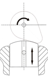
When higher valve lifts are necessary and durability is an issue, however, this extra valve lift can be obtained using a more pronounced curvature of the tappet, which is pegged in the tappet bore and, although free to move up and down, cannot rotate. To even out valve seat wear, valve rotation can be encouraged in other ways, but the 'domed' tappet face ensures that the contact point with the cam will always stay within the tappet diameter.
Surprisingly reliable and a bit like a 'Get Out of Jail Free' card, the domed tappet can sometimes help designers get out of the rut.
Fig. 1 - The domed tappet
Written by John Coxon
4394