Hydraulic tappets
 In the OE roadcar business, where noise and cost of ownership are major barriers to many prospective buyers, the hydraulic tappet has much to recommend it. But in the world of motorsports, where lightweight and efficient valvetrains are most desirable, their use is generally viewed with disdain - or so I thought until recently when, via the industry bush telegraph, I heard of a particular race team owner actually specifying hydraulic tappets in his latest engine.
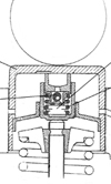
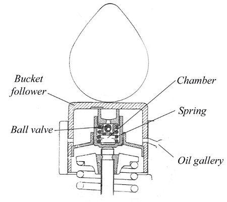
To recap, a hydraulic tappet for an overhead cam engine generally consists of an inverted bucket follower body incorporating a plunger, which is guided by a sleeve. Inside the plunger there's a loose spring, a ball check-valve or plate and a thrust pin, which also slides within the plunger.
Oil under pressure from the main engine oil gallery finds its way into the chamber and expands the assembly such that the traditional valve lash clearance normally seen in purely mechanical systems is taken up, and the inverted bucket runs against the cam profile for the whole of its rotation. Open to oil gallery pressure when the bucket is running along the base circle of the cam, when the bucket begins to move the oil inside the chamber is sealed off from its supply and, being almost incompressible, transfers its motion through to the engine poppet valve and spring assembly.
While all this might sound fine, hydraulic tappets of this type have some inherently undesirable characteristics. First, and probably most obvious, they are much heavier than mechanical tappets. Second, and perhaps more significant, they suffer from what is known as 'leak-down' when the oil in the chamber, no matter how little, inevitably escapes.
Third, hydraulic tappets can have a tendency to 'pump up' when engine speeds approach that of 'valve float'. As this happens, the valve may not return back to its seat quite so positively and the engine may lose power momentarily. To combat this effect 'anti-pump' tappets have been devised that generally include a form of internal snap ring to limit the movement of the cup within the tappet and keep control at high speeds.
Given all these disadvantages however, there was nothing I could find that would make me choose hydraulic tappets over mechanical versions until I looked at a third type of hydraulic element more usually described as the variable duration type. In this design, rather than 'leak-down' the tappets are purposely designed to 'bleed down' during use. This carefully controlled leakage inside the tappet allows the mechanism inside the tappet to move slowly as the bucket is rising, the combined effect of which is to limit both the duration of valve lift and the lift itself.
The net effect at slow speed is to simulate a cam timed better to the demands of the engine at this speed with little or no valve overlap. As the speed of the engine increases, this 'bleed-down' effect - which takes time to occur - is reduced, and the cam lift and duration rises back to more normal levels.
Producing better throttle response and greater power at low engine speeds, the system operates in effect as a variable lift and duration camshaft. When engine speeds are limited (to about 7000 rpm) anti-pump technology can also be used.
In theory at least, and in formulae where valve lift and engine speeds are restricted, there could be an argument for using hydraulic tappets. Sounding a little noisy at low engine speeds when the tappet is effectively collapsing, in the right application and carefully calibrated, these might actually work.
As a purist, however, I much prefer the lightweight mechanical systems.
Fig. 1 - Typical hydraulic valve cross-section
Written by John Coxon