Location of con rod caps, part 2
 In the previous article on the subject of maintaining the accurate locations of the two parts of a split con rod design, we looked at dowel pins and ring dowels, and the relative merits of the two methods.
The subject of joint shear stiffness was raised, and it was noted that the ring dowel, having a greater cross-sectional area, provides more stiffness to the joint. A stiffer joint is more stable and less likely to suffer from joint face fretting wear. While the con rod bolt may not have come undone during service - nor indeed lost an appreciable amount of pre-load - there is often evidence of small-scale movement, as shown by fretting damage.
There is therefore some merit in minimising the amount of fretting damage, or in engineering its complete prevention, and this is effectively taken care of by increasing the shear stiffness of the con rod joint. Increasing pre-load will be helpful, and providing a thicker ring dowel would also be working in the correct direction. However, this may require a heavier bolt, and more joint-face contact area; we would also need to move the bolt axis further away from the big-end axis, increasing the bending stresses on the bolt.
So, while increasing load and stiffness might be working in the correct direction to solve the problem, we will often invite further trouble by doing so. Far better that the engineer should consider practical ways to use the smallest suitable bolts and look towards geometrical solutions to the problem in hand.
For a number of years, some con rod manufacturers who make rods for production vehicles have produced 'cracked' rods. A production con rod, generally made by sintering of powdered steel, is made and a notch is deliberately introduced such that, if the rod is subject to a sudden impact in the correct location, a brittle fracture is produced running across the rod at the big end axis.
This brittle fracture surface, having failed with no elastic deformation, is complex and random, and the two halves locate together perfectly. Moreover, the method is more economical to produce than a conventional rod, as there aren't any joint-face machining operations to consider.
In producing a con rod from a high-strength steel, we are unlikely to be able to produce the same phenomenon of brittle cracking and so, if we seek to produce a similar effect, we need to do it on a larger scale by machining. There are a number of companies producing con rods who can accurately machine serrations into the joint face.
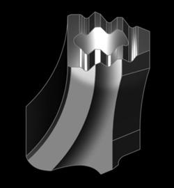
The most popular method is to produce a number of serrations in a similar form to a rack-tooth profile, running parallel to the big-end axis. These lock the rods together in one direction, but to avoid relative movement of the rods in a direction parallel to the big-end axis, a pin or dowel is still required. An example of a serrated rod split face can seen in the accompanying pictures. For the serrations to mate together great accuracy in manufacture is required.
Fig. 1 - 3D detail of serrated rod split line (Courtesy Zzuhl/Arrow Precision)
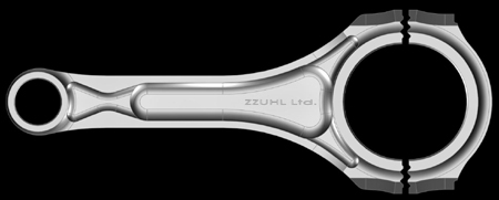
Fig. 2 - Con rod incorporating a serrated split line through the big end (Courtesy Zzuhl/Arrow Precision)
Written by Wayne Ward
4406