Rod thrust face design
In terms of controlling the axial position and axial float (in a direction parallel to the crankshaft axis) of the con rod, there are two main methods of achieving this - crank-guided rods and piston-guided rods. As you may discern from the descriptions, the first type thrusts against the crankshaft, the second type against the piston. Crank-guided rods remain the most popular type for many kinds of race engine. Commonly, the contact between the crank and rod thrust faces is one of annular contact defined by two annular faces.
Where plain annular contacts are used, we are only able to generate pressure in an oil film due to 'squeeze film' operation - that is, where there is a decreasing clearance between the two annular surfaces. Otherwise, we rely on enough lubricant being forced through the contact to prevent metal-to-metal contact. There are a number of design features that can be employed on the thrust face of the con rod to allow hydrodynamic lubrication to become established. Very little thrust area is required as the forces, and thus stresses, involved are only very small. A full annulus is generally used because people are comfortable with this solution, especially given the difficulties in generating pressure in the oil film.
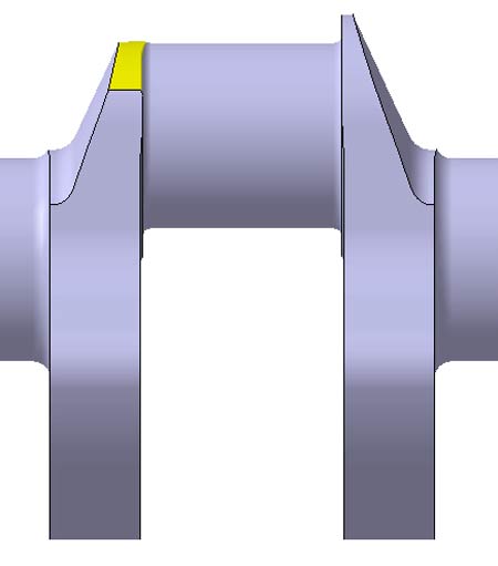
However, we are not limited to producing a full annulus on the crankshaft to bear against the con rod thrust face, and there are a number of reasons to consider something other than a complete annulus. Most obviously, there is a weight saving to be made, especially if a portion of the thrust face is removed at the furthest distance from the crankshaft axis. Not only can this weight saving be realised, but weight on the opposite side of the crankshaft axis can also be saved as there is less mass to balance. Fig. 1 shows the sort of material removal that might be considered if weight is to be removed from the outer part of the rod thrust face on the crankshaft.
Less obvious is the fact that equally significant mass savings, accompanied by very useful reductions in stress concentration factor, can sometimes be made by removing part of the rod thrust face on the crankshaft at the point closest to the crankshaft axis. By removing the innermost part of the thrust face, we can create a more generous fillet radius, especially where we undercut the crank web. Undercutting and removing material from the crank web, when done judiciously, is a proven method to reduce stress concentration. I would refer the reader to Taylor*, which neatly summarises earlier work by other engineers on the subject of crankshaft stress concentration.
Care must be taken when interrupting the rod thrust face on the crankshaft. Careful detail of the leading edge of the thrust face is required to prevent wear. The edge should not be left sharp.
Another advantage of not having a complete annular thrust area is that such a design is actually likely to provide the hydrodynamic oil film which is impossible to create between parallel flat surfaces.
* Taylor, C.F., "The Internal Combustion Engine in Theory and Practice", vol 2 (Combustion Fuels, Materials, Design), MIT Press, 1985, ISBN 0-2627-0027-1
Fig. 1 - Reducing the thrust area between the crank and rod can bring a number of benefits, including lower crankshaft mass and inertia. Compare the left side, having reduced thrust area, with the right
Written by Wayne Ward
6103