Control electronics for the ERS-K and the ERS-H
The advent of Energy Recovery Systems (ERS) in Formula One since 2009 has brought a new breed of electronic device into the sport, the ERS control electronics (CE). With Formula One’s greater exploitation of ERS for 2014, and with only five CE units allowed for the year, the CE has become very important.
The function of the CE is to control the ac three-phase power of the Motor Generator Units (MGUs) and the dc power from the battery. Currently Formula One uses two MGUs, one for the kinetic system and one for the heat system, where the kinetic system is an upscaled version of the recent KERS and the heat system is attached to the turbocharger. To control these two systems two separate CEs are used, appropriately termed CUK and CUH.
Inside the CE there are two sides to its operation, a low-voltage side, with logic boards controlling the high-voltage side with switches, and capacitors switching the power between the MGU and the battery.
When harvesting energy, the relevant MGU will send its ac power via three high-current cables to its CE. Inside the control unit’s casing is a series of high-current switches called IGBTs (insulated gate bipolar transistors) that switch the current, which also passes through capacitors. The electronics here convert the current to dc format.
The CE then sends the dc power via two cables to the battery. By inverting this process the CE can also take battery power to spin the MGUs.
This process of converting from ac to dc and back creates heat and therefore losses. Keeping the electronics at their working temperature is critical for reliability, and air cooling alone is not sufficient to manage the heat rejection so this is achieved with a dedicated water cooling circuit, which requires a small pump and radiator mounted in the sidepod.
Conveniently, the CEs provide the car with its 12-24 V supply for the car’s other electrical systems, so the car does not need an alternator or its own battery.
Where to mount the CEs in the car is decided between the power unit manufacturer and the teams, so installations vary, with the units mounted either with the battery in a recess under the fuel tank or on the sidepods, depending on the team’s philosophy on fuel tank size and its impact on wheelbase length, cooling and sidepod packaging.
New rules limits team to five complete power units for each season, and from 2015 just four. For practicality purposes the power unit is split into six elements, one of which is the CE for the ERS. Should a team fit a sixth CE then there will be a grid penalty for the driver, with further penalties for further new units being used.
This places great importance on reliability, despite these power units being all-new for the 2014 season. At the season’s halfway point, several drivers had already used four CEs, the CE itself proving to be an unexpectedly unreliable part of the complex new power units. Teams have reported that any failure in the CEs tends to be on the high-current side, not the lower-voltage logic boards. The result of high-voltage spikes tends to be catastrophic on the internal components and render the CE unusable.
Although the reliability of the CEs had improved in the latter part of the first half of the season there will be drivers who suffer penalties as a result of these units.
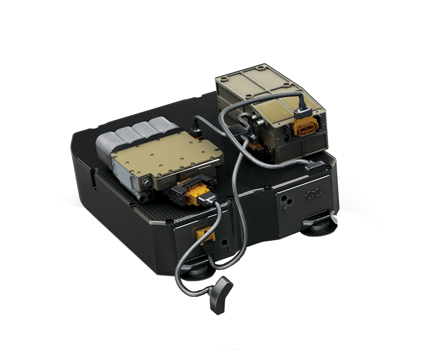 Fig. 1 - A typical CE unit with the capacitors and high-current cabling evident
Written by Craig Scarborough
7249