Liners - top or bottom?
After having written a number of articles on some interesting engine projects, especially in the field of amateur racing, this article will give some more background on an internal aspect of engine design - cylinder liners.
In deciding on the best liner design for an engine, a number of boundary conditions need to be evaluated. First, a conceptual decision needs to be made between whether the engine will use parent bore (bore in the base block or cylinder material), dry liner (liner assembled into base block or cylinder, without direct contact between coolant and liner) or wet liner (liner assembled into base block or cylinder, with direct contact between coolant and liner).
When a race engine has been derived from a production engine, this decision has already been made for us. While production units will sometimes be re-machined to convert to wet liner, this is not done very often, so I'll assume here that the decision has been made to opt for the wet liner concept. But one question remains: top or bottom?
When evaluating the concept of a wet liner design, a number of layout considerations need to be into account. For example, the chosen liner concept can determine the length (and therefore mass) of the engine. In order to understand this better, let us first look at the three major liner concepts - top, mid and bottom stop. It's assumed that the cylinder head sealing surface is called the top end of the engine.
The top-stop liner concept is so called because it has a flange on the top of the liner with which it is located into the cylinder block. The mid-stop has a similar flange at or near the middle of the liner, and the bottom stop has its locating flange near the lower end of the liner.
First, let us take a closer look at the main differences between these three concepts. In principle, the assembly process requires the top to have a larger diameter than lower down, so for a given liner wall thickness (depending on peak firing pressures) and liner locating surface width, the top-stop design requires the least space. This means the overall length is influenced by the chosen liner concept. Every additional millimetre means additional engine mass, so the liner concept is seen as an important decision parameter in engine design.
Apart from geometrical effects, engine cooling needs to be considered, in this case the area where liner cooling is required most - the top end of the liner, where combustion takes place and temperatures are highest. To get the coolant as near as possible to the combustion chamber, the wall thickness needs to be as small as possible, which would favour the mid- or bottom-stop concept.
A third important point is deformation of the liner over its length, in relation to the oil consumption and friction losses of the piston system. The lower the deformation, the lower the piston ring pre-tension that can be chosen (lowest friction losses). To have as little deformation as possible coming from the assembly forces of the cylinder liner onto the liner (by pre-tightening the cylinder head bolts) the top-stop concept is favourable.
With this design, the liner is not being pre-tensioned at all and will therefore not deform due to the loading of the clamping pressure. However, due to the proximity of the cylinder head bolts to the liner flange in this design concept, one should be careful not to distort the roundness of the cylinder bore. With a liner concept with no direct contact between the top surface of the block and the liner flange, this radial distortion will be limited.
Given the points above, it's easy to see that deciding on the liner design concept requires some prior work in order to balance the pros and cons of the several options.
After the conceptual decision has been taken, there are a number of secondary decisions, such as:
" Sealing ring position or coolant jacket length - this being in relation to coolant system volume
" Sealing ring geometry - simple O-ring of formed sealing ring; related to ease of assembly of the rings and assembly of the liner into the engine block
" Location of the sealing rings - engine block-sided or liner-sided; related to overall required space and assembly of the liner
" Sealing of the top end of the liner, in the case of the top-stop sealing concept - radial sealing of the flange or liner portion below the flange, axial sealing below the flange, and of course
" Radial location of the liner - radial on the flange, or directly below the flange
And apart from these geometrical items, the liner's material is also open to some more thinking in order to decide on the best compromise.
Covering these secondary items is beyond the scope of this article, so I'll focus on them next month, in order to provide the whole spectrum of decision-making on cylinder liner concepts.
As can be seen, there is no single best cylinder liner design concept, it all depends on which of the parameters are given which priority. And, of course, whether you can start from a clean sheet of paper or a production engine will be used as a basis. As mentioned many times by many engine designers, the engine, in all its complexity, will always be a compromise; in this case - top or bottom?
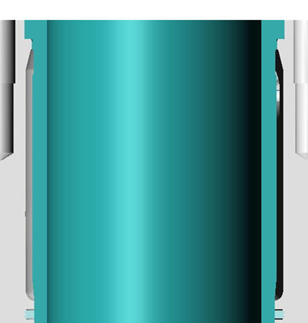
Fig. 1 - Top-stop liner concept, including lower sealing ring
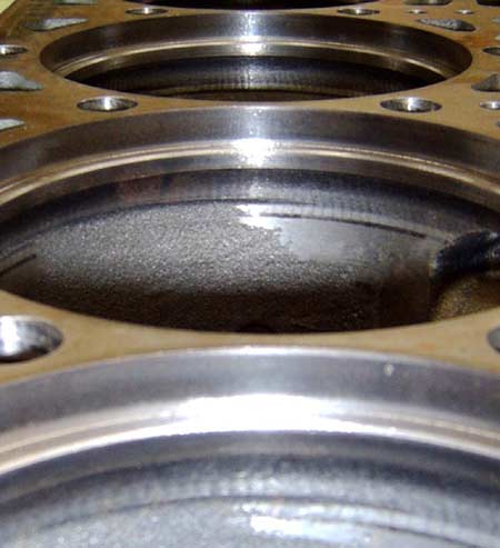
Fig. 2 - Detail of machined engine block for top-stop liner
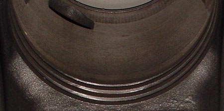
Fig. 3 - Detail (bottom) view of machined liner interface in engine block
Written by Dieter van der Put
7325