Liners - top or bottom (part 2)
The previous article on this subject described the concepts and decisions to be taken when applying a wet liner, and concerned the choice between top, bottom or mid-stop liner. Some basics were shared on the advantages of each one, and it was mentioned that a number of secondary engineering decisions need to be taken to establish the final design. This follow-up article will provide some more insight into these secondary decisions.
Let us take a closer look at some of those decision areas:
• Sealing ring position/coolant jacket length
• Sealing ring geometry
• Location of the sealing rings
• Liner material
• Radial location of the liner
The first three all concern the actual shape, location and orientation of the non-combustion side sealing rings (assuming formed engineering plastics sealing rings are used, in whatever section). In general, the coolant will be located as close to the combustion gases as possible, in order to achieve maximum cooling at the desired location. This dictates the required top level of the coolant jacket. The lower level is typically based on the top level minus the piston stroke. The goal is to have coolant in proximity to the piston rings throughout the total travel of the piston, although the lower level is taken somewhat more flexible than the top level. When the block structure prevents having a full coolant jacket, the accepted compromise is to have piston rings below the coolant jacket. Since the heat transfer is much higher at the high temperature area this is an acceptable situation.
As regards sealing ring geometry, some people choose simple O-rings while others opt for non-symmetric sectioned sealing rings or even X-type section rings. The choice remains a personal thing, I guess.
The location of the sealing rings, in the block or on the liner, can be more significant for the engine design. With the sealing rings in the block, proper assembly of the rings is more difficult than on the liner, but because the base of the liner can be smaller (in diameter) then the top flange can be kept smaller, leading to a more compact block.
Another significant parameter is the material from which the liner is made, the principal choices being steel or cast iron. The choice will be based mainly on maximising heat transfer and geometrical stability. In order to keep the engines as compact as possible, thin walls are preferable, for which a material with a high E modulus, like steel, will be chosen. But in order to maximise cooling, a material with a high thermal conductivity is preferable. As usual, not many materials combine the both of best worlds, so a balance will need to be found between strength/wall thickness and thermal behaviour.
One of the final significant parameters in determining the liner design is the decision about where the liner will be positioned radially. A liner needs a radial fit, and if it hasn't been engineered carefully, this can result in excessive oil consumption or even major engine damage.
At the top end there are in principle two possibilities for radially supporting the liner - either on the circumference of the flange or just below it. When choosing a radial fit just below the flange, one must make sure that the fit does not cause deformation of the liner, which would lead to contact issues with the piston rings. The upper flange solution is less risky, since typically the flange height is lower than the distance between the top piston ring and the piston crown. In this case, the piston rings will not get into the area where the fit could lead to deformations.
When choosing between a bottom or middle radial fit, there is still the risk of piston skirt scuffing or increased oil consumption. It has proven to be very difficult to maintain liner cylindricity in such situations. All possible engineering measures to increase robustness in this area will lead to a reduction of overall efficiency. One possible solution - increased ring pressure for the piston rings to be able to follow the liner shape - will lead to higher friction losses, while another option, increased piston skirt clearance, will lead to more piston slap and increased wear rate of the piston system.
The design areas covered here can all be simulated pretty well using FEA, and will lead to well-founded decisions regarding the liner concept. Since most production engine blocks these days feature linerless concepts with coated bores, the number of engineers needing to make decisions on wet-liner concepts will be limited. However, having some knowledge about these kinds of basic engine design will lead to increased understanding of the pros and cons of the liner concepts and their influence on overall engine design.
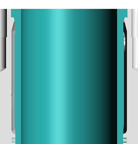
Fig. 1 - Top-stop liner concept, including lower sealing ring
Written by Dieter van der Put
3022