Turbocharger speed measurement
In the inexorable search for increased power with efficiency, engine manufacturers are looking more and more towards the turbocharger in its various forms. Twin-turbo engines, sequential turbos and even engines using dual boost systems – two compressors and one turbine on the same shaft – are becoming more common, and because of this the engine tuning industry is having to understand the limits to these units much more precisely.
The accepted limits on the operation of a turbocharger are compressor ‘surge’, where for a given airflow the pressure ratio is too high, compressor ‘choke’ – the point where maximum flow is achieved (at reduced compression efficiency) – and maximum turbo speed. Whereas compressor surge can be determined aurally, and choke by the compressor outlet temperature (where the limit is around 60% adiabatic efficiency), turbocharger speed has to be measured. For a shaft travelling at anywhere between 60,000 and 300,000 rpm, depending on the diameter of the compressor wheel, this can be a challenge.
There’s a story about a philosopher who claimed he could tell exactly how many horses were in a field just by looking at them. Dumbfounded and yet intrigued, his companion pointed towards a coral where 29 of his best stallions were simply milling around awaiting sale. Upon guessing correctly and being asked how he came up with the correct number the philosopher said, “It’s simple really – I counted the legs and divided by four” which of course is exactly the same way we go about measuring the speed of a turbocharger. Simply count the number of times a blade passes a certain point in a given period of time and then divide by the number of blades per revolution passing. Simple or is it?
The first thing to remember is that any electrical instrumentation anywhere near the turbine wheel will simply not be durable. Electronic sensors rarely work reliably at much over 80 C. And even though some sensors these days claim to work at temperatures well above this, it is simply not possible to measure the speed of the turbocharger at the turbine wheel when the turbine casing is glowing red hot.
At the other end, that of the much cooler compressor, the wheel is almost invariably made from a non-magnetic aluminium alloy. That means a magnetic pick-up fixed into the compressor casing to detect the compressor blades as they pass is out of the question. The only way to calculate turbo speed would seem to be to use either a magnetic nut (not entirely practical for a permanent installation) or some kind of eddy current/optical device measuring the passing of individual blades. The output of such a sensor, when connected to some kind of signal conditioning and fed into a data logger, will give an average speed accurate enough for confirming the engine airflow data on, say, a fuelling map.
However, to determine the instantaneous speed of the turbine, for instance in the cast of a burst test, this requires a slightly different technique. Here the signal output from the sensor (or magnetic nut retaining the compressor wheel on the shaft) is recorded and fed back across the Y-Y terminals of an X-Y oscilloscope. With a known frequency applied across the X-X axis, the resulting output produces the phenomenon known as Lissajous figures. By altering the frequency and phase of the X-X input, a point will be reached when a perfect circle is produced on the screen, and at this point the known frequency will be the same as that on the Y-Y plates but 90º out of phase, and hence the precise burst speed will be known, compared with only the average over the timing interval by the other method.
Convenient it probably isn’t, but a burst speed of say, 267,532 ±1 rpm rather says it all.
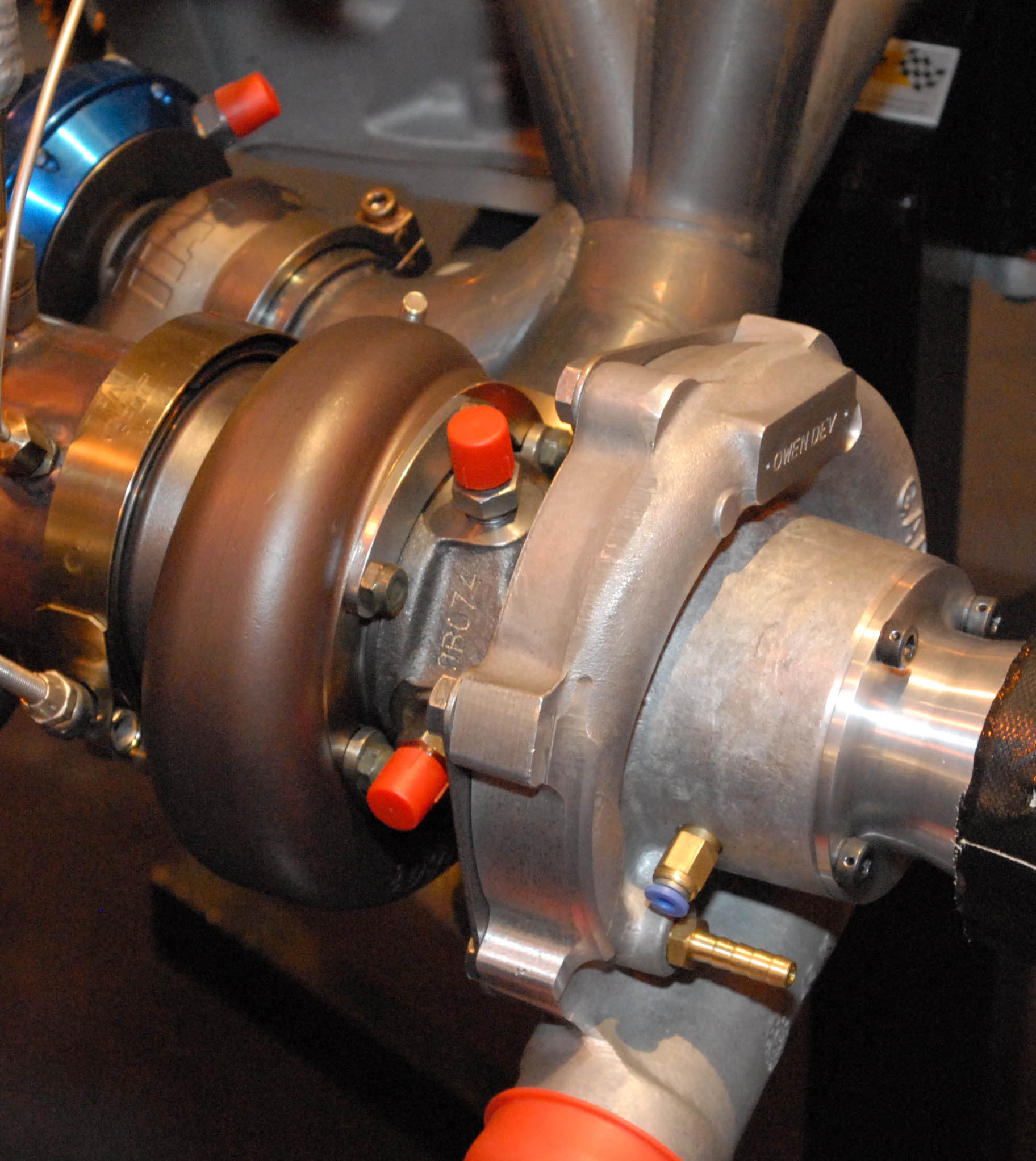 Fig. 1 - Turbocharger
Written by John Coxon