The heat is on
 One of the most difficult tasks for an experienced dyno engineer is to measure the amount of heat rejected to the engine coolant. On the face of it, fitting thermocouples - one in the engine water going in and another as it comes out and then measuring the coolant flow rate, would seem a simple enough task. But when we analyse the accuracy of the instruments used, the level of uncertainty calls for a more considered approach. The problem, as you probably appreciate by now, is not the accuracy of any particular flow meter to be used but measuring the coolant temperatures both going in and out of the engine.
In the design of any heat engine where fuel is burned, a thermal gradient inevitably exists across the unit. This gradient brings with it thermal expansion of the metals used, creating distortion and internal stresses over and above those caused by the pressures of combustion and component dynamics.
To dissipate this heat, the flow rate of the coolant can be increased, at which point the temperature rise across the engine will fall. But in doing so the power required by the coolant pump will increase and may eventually affect the effectiveness of the heat transfer between metal and water as a result of rapid changes in localised velocities, cavitation and so on. To avoid this, engine designers prefer to design the pump such that the temperature rise of the coolant across the engine is somewhere near 4-5 C when the engine is running at full load. This balances the power required to run the pump against the thermal stress introduced in the engine.
But this is where the problem starts. Trying to measure the exact temperature of both the coolant inlet (at about 78-80 C) and outlet (consequently at 82-85 C) to give an exact temperature difference to within 0.1 C is not easy. A mercury thermometer, carefully designed and calibrated, will probably do the job reasonably well, but they are not easily integrated into data-logging systems, and gone are the days when engine testers will even enter the test cell when an engine is at full chat.
The most obvious choice by some would be to use a simple thermocouple. A type 'K' Chrome / Alumel would give a useful level of sensitivity, at about 40 microvolts per degree C, but it is when we look at the measurement error that the alarm bells ring. As installed against an electrically generated reference temperature, the typical measuring error will be as much as ±1.5-2 C across randomly selected units, falling to ±1 C across the same batch.
With an error such as this on each temperature measurement, the error in computing the heat rejected to the coolant could approach 40-50%. Careful calibration will of course improve on that, as well as wiring the thermocouples 'back-to-back' to measure the temperature difference, but for a general-purpose thermocouple that needs to be robust enough to withstand the rigours of the engine test bed, the type 'K' is hardly suitable for such accurate work.
For more accurate readings, resistance temperature devices - the most common of which is the Platinum Resistance Thermometer - are much more accurate, but since they use sophisticated electronic circuitry they are also more expensive. In three- or four-wire form, and when carefully calibrated, accuracy can be as good as ± 0.03 C, but when wired to give a differential output between the inlet and outlet temperatures of the engine coolant, the overall heat-to-coolant error is much more acceptable.
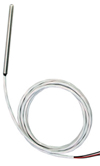
Fig. 1 - Three-wire Platinum Resistance Thermometer
Written by John Coxon
3234