Transmission and driveline offset
 One of the problems faced by race car designers is the conflicting requirement of keeping a low centre of gravity for the engine (and transmission), whilst keeping the driveshaft within acceptable values. Whatever the chosen method of coupling excessive angularity will lead to increased power losses and ultimately, failure of the joints.
Putting some numbers to this, consider a Formula Three car whose engine is dry sumped and running a 140 mm diameter race clutch on a lightweight flywheel. It will have a crankshaft axis that is less than 100 mm above the bottom of the engine. Running with Avon slicks at the rear, the drive flange on the rear hub will be approximately 285 mm above the contact patch. If the car is running at 30 mm rear ride height, then that gives a 155 mm step up height between the crankshaft and the final drive output flange. A conventional, in line, longitudinal transaxle, with drive entering through the lower shaft and exiting through the upper will typically have shaft centres of just over 3 inches - around 78 mm. The rest is taken by driveshaft angularity. This can be reduced by making the offset between the differential and output flanges as small as possible, and the rear track as wide as possible.
On a relatively low powered race car, and within modern machining techniques employed in finishing the tripod joints, this is something that you can 'get away with', but on higher output race cars this is usually not the case.
Designers have therefore consistently looked beyond the simple twin shaft transaxle in an effort to reduce the size of the offset - and the problem. One solution is to introduce a step up gear into the assembly, either in initial design or as an add on. Depending on the requirements of the car, this gear can be positioned at several different points along the drive line.
Positioning it immediately after the clutch will lift the complete gearbox assembly aft of this by a proportion of the step up gear centres, the exact figure depending on whether the gears are arranged to sit above one another. This might benefit the ground effect tunnel area on a full ground effect car by reducing the size of the 'bump' needed to clear the diffuser roof, but it will also raise the transmission CoG, therefore negating to some degree the benefit of a shallow sump and small diameter flywheel. The input shaft would also be very short and therefore liable to weaken under shock loading.
The alternative, of placing the step up either just in front of, or maybe behind the final drive, will produce the exact opposite set of gains and losses. As ever, there is no one correct answer in race car design, everything is a compromise.
Another solution, which saves the additional weight of the step up gears, their bearings and so on, is to employ a hypoid bevel final drive. On paper this always looked quite attractive, and was used in Indycars quite extensively in the 1980s, where the rear tyres were 28 inches diameter and the conventional Hewland DG gearbox featured only a 3 ½ inch shaft centre. The downside was the requirement for a more sophisticated lubrication system and the special oils needed for the hypoid. These gearboxes fell out of favour after a certain amount of unreliability - they were also quite expensive to manufacture. As an aside, it was also possible for the drawing office to produce a single speed with 5 reverse gearbox by getting the hypoid on the wrong side of the crown wheel, but this could not be corrected by flipping it over as on a conventional pinion gear. Not that this ever happened of course….
A more pragmatic approach, which again has a certain elegance on paper, is to tilt the complete engine and transmission assembly up about the nose of the crankshaft - typically between 1 and 3 degrees of tilt would be used. The Arrows A2 Formula One car employed this, primarily to clear the ground effect tunnels, and it was common in Indycars as well. Again, this lifts the whole CoG of the transmission and engine again, and in that respect is slightly illogical.
Perhaps the best answer comes with the use of a transverse box, for then the gear trains can be so arranged that the final drive comes out more or less where you require it - the step up gear is necessary in any case to turn the drive through 90 degrees.
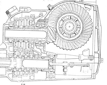
Fig. 1 - An early hypoid final drive in the Lotus 12.
Written by Peter Elleray