Cool bubble
 In this article I want to emphasise the non-material side of the cylinder head, focussing on cooling. Whereas in previous articles I have provided some insight into cylinder head structure and coolant flow, this time I will look at cooling mechanisms in the cylinder head.
The unceasing demand for higher specific power has enforced higher operating temperatures on engine parts, in particular cylinder heads, which has a significant effect on thermo-mechanical loading and consequently on mechanical damage. The cylinder head is one of the critical components of a high-performance race engine that is subjected to complicated thermal and mechanical loadings. Temperature distribution and gradients lead to thermal stress, and could eventually lead in turn to thermo-mechanical fatigue of the cylinder head.
As was briefly touched upon in an article by John Coxon in the May 2010 issue of RET-Monitor, the cylinder head coolant system relies on a mechanism called nucleate boiling. John mentioned that the localised temperature of the surface exceeds the localised boiling point of the transport fluid, so nucleate boiling occurs at the boundary. "This is good, and can actually increase the heat dissipation at that point," he said.
First, let me explain that boiling is the formation of vapour bubbles at the heating surface. The boiling heat transfer is sensitive to the temperature delta between surface and liquid. In addition, the heat transfer coefficient is affected by the local vapour-liquid mixture ratios and flow velocities.
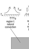
A typical boiling point curve is shown in the attached figure. Up to point A, heat transfer occurs by natural convection, so no boiling occurs. From point A, the surface temperature is high enough to activate nucleation sites, usually around the combustion chamber and exhaust valve area, and vapour bubbles are formed. Heat transfer increases due to the very rapid, almost explosive, formation of the bubbles which causes a very strong local velocity within the liquid film. In this phase, large numbers of bubbles form on the hot surfaces and travel through the bulk of the coolant, later condensing as they move to a lower temperature region, distributing the heat into the coolant.
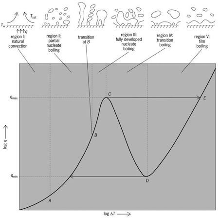
The increased heat transfer reduces the cylinder head surface temperature and increases energy added to coolant. In the region from A to C, more bubble nucleation sites are activated - this is the region of nucleate boiling.
As you can probably understand, the design of the coolant system in total - and specifically the coolant system in the cylinder head - requires significant development time, effort and experience. In order to predict heat transfer in the cylinder head, 3D CFD and FE analysis is used, in combination with 1D modelling. 1D models are typically used for well-established flow without swirl and measured over certain lengths with constant cross-sections.
In this case, however, these models have to be applied to swirling, accelerated and undeveloped flows in non-constant cross-sections, as in cylinder heads. Here, flow behaviour may differ significantly from that in straight sections. Therefore, 3D simulations are used to investigate local behaviour and flow effects. Based on these 3D simulation results, 1D empirical models can be developed to improve accuracy, while still achieving the required short process lead times, leading to cylinder head coolant system predictions being available early in the development process.
The nucleate boiling mechanism is very sensitive to a number of parameters, such as coolant system pressure and temperature, coolant flow velocity and cylinder head material. Working on high-performance engines, the deeply rooted drive to achieve the highest efficiencies is what makes us tick, so we use high-temperature, high-pressure coolant systems - all in order to keep coolant heat exchangers as small as possible, and packaging space as aerodynamic as possible.
With these parameters already on the engineering extremes, might there be an opportunity for looking at the cooling fluid composition?
Fig. 1 - Typical Boiling Curve (Courtesy of The McGraw-Hill Companies)
Written by Dieter van der Put
3227