Follower friction
In these days of soaring fuel prices the top priority for any engine manufacturer is the responsible use of scarce resources. Specific fuel consumption or the amount of fuel used per unit power output per hour is the measure of the task, and a major enemy of this is friction. But when it comes to low-friction engines the experts in this field are not, as you might expect, from the race engine industry No, the real experts in this area, in my opinion, are the OE engine manufacturers, whose search for that extra 0.1% fuel saving (wherever it comes from) is both inexorable and painstaking.
With the penalties measured not only in lost kilowatts but in punitive governmental fines in the form of tax, the focus on the mixed lubrication regime that is the valvetrain is now as intense as never before. And when you appreciate that the vast majority of race engines are developed from those originally designed for the road, then the sooner we get to grips with these roller finger follower (RFF) designs the better.
For many a long time the direct acting mechanical bucket (DAMB) valvetrain has been the staple of the performance engine valvetrain. Simple, compact and therefore exceedingly stiff, its limitations are well understood, as indeed is the amount of friction generated by the relative sliding of the tappet in its bore and the face of the cam as it slides across the tappet. Much better designs, at least from a friction perspective, are those of the RFF and roller rocker arm (RRA). RRA designs, although they produce shallower cylinder heads, tend to have an inherent lack of stiffness in the rocker arm, so no wonder more and more manufacturers opt for RFF designs.
Not as stiff as the DAMB but better than the RRA, these rolling contact designs do have major downsides though.
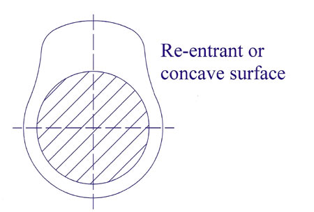
The first of these is an inherent disadvantage of any rolling contact when the contact stress between two curved surfaces is much greater than that if a curved cam meets the flat (or very slightly curved) surface of a bucket tappet or finger. Because of their size, these Hertzian stresses can therefore limit the choice of material, making cast iron undesirable. However, even in using the best of steels, a larger nose radius will be necessary, which in turn for modern high lift and rapid opening/closing will require the use of 're-entrant', concave or kidney-shaped cam profiles to be ground on its flanks.
The process of grinding 'normal' cams uses a comparatively large grinding wheel (between 400 and 600 mm in diameter). The larger this wheel is then the lower its wear rate and the less time required for 'dressing' it during the grinding of the cam. With cycle times measured in seconds, the quicker a cam is ground the less expensive it is since, as we all know, in manufacturing, time is money. But large wheels are no good for re-entrant cams, since large wheels limit the radius of re-entry, effectively limiting the opening/closing speed of the valve. Cubic boron nitride wheels can reduce this diameter to as little as 50 mm (some grinders claim down to 34 mm) but even so the inevitable increased cycle time on the grinding machine increases machining time and adds much to the cost.
So while roller finger followers save friction and therefore fuel, you pay for it all in other ways.
Fig. 1 - Typical re-entrant or kidney-shaped cam profile
Written by John Coxon