Future cracked
Defined as "a device supporting a mechanical component and enabling relative movement to another with the minimum of loss of power", a bearing is not just about the selection of the most appropriate material but also - you might not be surprised to learn - about its shape. So while the fatigue strength, embeddability, resistance to wear and seizure are all important, the running clearance between the journal and bearing surface is equally important. This is especially so as engine oil films become thinner.
At its most basic level, this running clearance can be described as the difference between the journal diameter and that of the traditional shell bearing at 90º to the parting line. For passenger cars with a nominal journal size of, say, 50 mm (2 in) this will be somewhere between 0.001 and 0.002 in, but as performance increases this is usually increased by up to 50% to take account of the extra flow and cooling needed. But with oil film thickness measured in microns, the importance of dimensions and shape in bearing design cannot be underestimated. And once machined to high levels of accuracy to produce the geometry desired, the objective is to maintain it under all conditions, both dynamic and thermal.
Take the case of a con rod, for instance. While the forces due to combustion will push down on the crankpin, those of an inertial nature will try to tear off the bearing cap as the piston disappears up the bore again. This cyclic load produces an extra-special challenge to the designer since the clamp load between cap and upper rod has to be sufficient to prevent movement of the cap. The traditional method of manufacturing is to machine the clamping faces of both cap and upper rod and then, bolted back together, machine the bearing housing diameter to the size required. This is time-consuming and consequently expensive, and to ensure accurate alignment during engine build it may require dowels concentric or offset, to the con rod assembly bolts. This will reduce the possibility of the cap moving - however slightly -under dynamic loading as well, and ensure the bearing stays accurately aligned throughout.
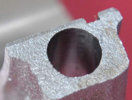
Nowadays, however, to ensure accurate alignment at less cost the method more frequently used in engine manufacture is that of fracture cracking. With this process the con rod is manufactured in one piece, and the intended big-end split line weakened in some way. Assembled on a jig fixture, the rod is split across this weakened point by a sudden impact, producing a clean break that will assemble back together accurately. Furthermore, the shape of the surfaces produced will give a considerable amount of lateral location, which will minimise any tendency of the cap to move or the bearing to 'walk' sideways during use.
Of course, not all con rod materials can be fractured in this way. Steels with any level of ductility are clearly unsuitable, and much development is ongoing to produce higher-strength steels with this brittle characteristic, but since production savings of the order of 25% are claimed don't be surprised if the traditional con rod and bearing cap arrangement becomes a thing of the past in OE engines in the years to come.
Fig. 1 - Fracture-split bearing cap
Written by John Coxon
4147