Hotter than ever
In my previous article I looked at the key differences between the former V8 and current turbo-powered Formula One engine blocks. The principal ones were far higher peak firing pressure and specific power, and because of these the main dimensions of the engine block have had to be modified in order to increase block robustness under these increased loads.
Another significant engine component that has a direct relationship with these increased loads is the cylinder head, so let us take a closer look at the consequences for the head, and which design modifications would be needed to overcome them.
In principle, every cylinder head has three major loads working on its structure – assembly (bolt loads), thermal and gas loads. In the previous article we saw that the maximum gas load has risen significantly, given the fact that the peak firing pressure went from 100 bar with the naturally aspirated V8 engines to more than 200 bar with the current turbo engines. Because of this we estimated an increase in bolt size from M11 to M14. The corresponding load on the cylinder head increases as well, and therefore the material thickness under each bolt head will need to be increased.
Since the bore of the engine has fallen from about 98 to 80 mm we already have a little less room for the coolant jacket, and because of the increase in material thickness another couple of millimetres is taken from the coolant jacket.
The other two loads have a direct relationship with each other and need to be balanced. On the one hand, the increase in peak firing pressure would require the flame deck of the cylinder head to be thicker, simply to withstand the bending of the head under these increased gas loads. Unfortunately, a thicker flame deck means the coolant is further away from the combustion temperatures, leading to higher material surface temperatures. And we mustn’t forget the fact that we were facing increased specific power, again a reason for higher flame deck temperature.
The most critical issue here is thermo-mechanical fatigue (TMF), which is damage of the material based on the differential temperature between hot and cold areas in relation to the material’s inability to expand and shrink freely under these conditions. The question now is which of the measures – increasing or decreasing the thickness of the flame deck – will be more important.
In this context the reduction of the bore by about 18 mm is helpful, simply because the increased gas load works on a smaller area. The resulting average load increase will be about 33%, a negative factor.
So what works in our favour then? Since the wall thicknesses of the ports are constrained by the casting process rather than design, there would be no reason to assume that these have decreased with the bore reduction to 80 mm. Therefore the structural function of these ports in the cylinder head (creating a kind of pillar between the flame deck and the upper deck of the head) has increased relatively.
On the other hand, cooling of the cylinder head needs to be improved because of the higher specific power (from about 225 to 300 kW/l). This increase will result in higher temperatures of the area around the exhaust valves and higher strain in the valve bridges between the exhaust and intake valves.
Another factor is the valve orientation, which is such that the exhaust valves are on one side of the engine and opposite to the intake valves. Thermal growth is more difficult to control in the longitudinal direction of the engines because the cylinders are next to each other. The internal material damage will therefore be greater because in this direction the head provides more resistance during expansion under temperature load, putting the highest strain in the intake-to-exhaust valve bridges. This, in combination with the fall-off in aluminium’s material properties under higher temperatures, means that reducing temperature in these areas is key.
Since the valve area is filling almost the entire bore, there are not many areas where the flame deck wall thickness can really be kept at its minimum. Looking at the very few pictures of Formula One cylinder heads that are available, I would estimate a wall thickness of around 8 mm as a minimum.
Not having any design experience specifically with Formula One engines, I am going to make an educated guess at estimating a reduction of up to 30-40 C flame deck temperature per 1 mm wall thickness reduction (getting the coolant closer to the combustion). These levels of temperature reduction will significantly improve resistance to TMF.
This is the main reason for me coming to the conclusion that the maximum effort, going from naturally aspirated V8s to the current turbo engines, must have been in reducing the flame deck wall thickness instead of increasing it due to gas loads, and I think the area between the valves has probably received the most attention.
We should not forget though that achieving these kind of reductions is not only how well one can design these critical areas but, even more important, how they can be produced – the cylinder head core packages must have been more detailed and more accurate than ever before. Hopefully it will soon be possible to write an article that focuses on these production processes.
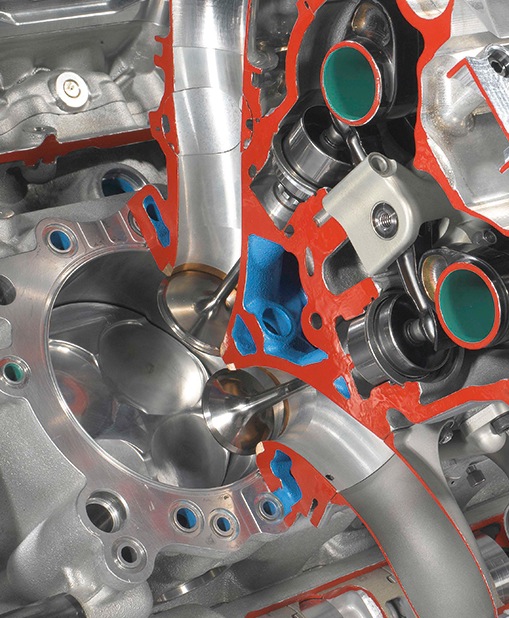 Fig. 1 - In red is shown the wall thicknesses between coolant and flame deck. As can be seen, there is no real homogeneous wall thickness, given the complex structure of the head (Courtesy of Toyota Motorsport)
Written by Dieter van der Put
7088