Improved interface between crankcase and block by using CAE
It has been a number of years now since many of the trial-and-error methods in engine development have been abandoned. Most of the higher class amateur racing teams and, without exception, all of the professional teams make maximum use of the available computer-aided possibilities that modern times offer. This includes not just CAD systems but also CAE applications such as finite element analysis (FEA) and computational fluid dynamics (CFD).
What is not yet so widespread though is the integrated use of the various CAE approaches. When several load cases (such as mechanical and thermal loads) come together, and perhaps fluids are involved as well then things become very complex, and a high level of experience is needed to make full use of CAE.
One of the more complex areas in engine design is the interface between the cylinder head and the crankcase. Granted, we all know we need to keep sufficient clamping load on the cylinder head gasket to secure sealing under all conditions, but what really happens to the cylinder head, crankcase, liners, pistons and so on under varying load conditions – and being able to predict what happens – is a different thing altogether. Trying to predict in which circumstances this interface is most critical requires a structured approach and, as well as skilled CAE engineers, sufficient computational power to get to realistic results.
First though we should clarify what we are trying to achieve. The main goal is to determine the deformations working on the interface, see which stresses will arise because of this and how the interface reacts to the loads under certain operating conditions. These conditions include not only firing (temperature and gas load) but assembly loads such as the interference fit of the valve seats and guides, as well as cylinder head bolt pre-load – and, if applicable, injector clamping loads. All of these will lead to cylinder head gasket deformation and stress.
Some typical load cases can be described which, in certain combinations, will be the most critical load case. Take assembly loads for example. The engine itself is in cold conditions and all components have been assembled with the correct bolt pre-loads and interference fits. This will lead to an initial stress in the components.
Then there is the temperature load, which depends on the temperature of the combustion gases as well as that of fluids such as oil and coolant. Certain deformations and stresses also occur here.
The third case, which is related to some extent to the assembly loads, is the load coming from external system effects – in this case, cylinder head deformation as a result of cyclic injector load transferred through the injector clamp onto the head. With gasoline fuel injectors these loads can be neglected, but with diesel injectors they can play a major role when combined with the other loads.
As a next step, the combined load cases that would lead to the most critical situation should be defined. Something that is often not considered is that one of the most critical operating conditions for the cylinder head gasket to perform its sealing function is when an engine is warming up. Everything is cold, so overall clamping load of the bolts onto the gasket is minimal, and combustion load is trying to lift the head from the gasket.
So, in these CAE simulations the related components are modelled, mostly in a CAD system, after which the components will need to be meshed (the creation of small elements within the components) for further use with CAE simulation tools. Meshing will need some attention, where typically the shape and size of the mesh is based on the engineer’s experience and will be tailored to specific analysis needs (smaller in areas of interest and somewhat bigger in other areas, all to reduce simulation duration).
The distribution of the temperature throughout the components, especially within the cylinder head and top end of the crankcase, then needs to be determined. Together with the heat transfer coefficients of the various materials in use, this will allow the stresses in the components to be simulated, as well as the predicted component and surface temperatures under the chosen – and most critical – running conditions.
When adding in the external system loads, which lead mostly to local stresses in certain areas of the cylinder head – as with high-pressure diesel injection – the overall stress levels can be simulated. The only thing left to do now is to determine the crank angle (position) at which the combined loads are critical. Here, some rather straightforward analysis will provide this type of information rather easily. Then the computational power comes into play, calculating the statuses of the separate elements in the mesh using finite element methodology.
Then, as a last step, post-processing the results allows us to determine which information is relevant. Mostly we would be interested in verifying the design and predicting the lifetime of some of the parts. This includes gasket pressure but also, for example, the liner deformation in order to predict oil consumption. Apart from this, critical temperatures could be subject to attention as well, such as the maximum temperature on the liner and piston top ring, cylinder head flame deck and many other areas.
I hope from this short summary that integrated simulation techniques have come a long way in being able to predict with greater accuracy what is happening inside an engine at critical interfaces. Some things are now becoming possible with hybrid systems, in areas perhaps even more complex than ‘just the internal combustion engine’ – a design we have been studying for more than 100 years now.
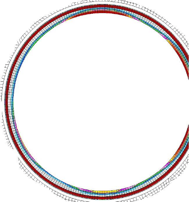
Fig. 1 - Cylinder head gasket pressure shown rotated over 360º of cylinder angle
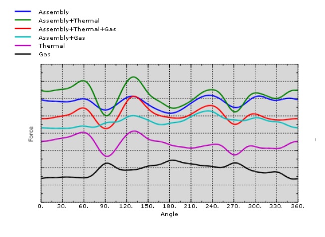
Fig. 2 - FEA result of local gasket pressure used to quantify sealing quality of the cylinder head gasket, in this case sealing of the combustion chamber
Written by Dieter van der Put
5551