KERS - Continuously Variable Transmission
 The continuously variable transmission (CVT) as used by Flybrid, is mounted between two clutches within the KERS unit. The clutches allow for disengagement of the CVT from the flywheel and the vehicle when not in use, and therefore minimises losses.
The only mechanism for controlling energy into or out of the flywheel is by controlling the ratio of the CVT. The CVT is responsible for the smooth variation of ratios. The CVT may sometimes be referred to as a Toroidal Continuously Variable Transmission
(TCVT), due to the shape of the rotating discs. The main components that make up the CVT are: the rotating discs, rollers, carriages, and the pistons (levers).
Each roller is mounted in a carriage and attached to a hydraulic piston. The pressure in the pistons can be increased or decreased to create a range of reaction torque within the CVT. The movement of the hydraulic pistons alters the angle of the rollers, where the angle of the rollers in relation to the centreline of the CVT controls the transmission ratio. This ratio affects the torque transferred through the CVT.
The operation of the CVT may be explained briefly as follows:
Between each pair of rotating discs there are three rollers, each roller is mounted in its respective carrier. When the vehicle brakes the electronic control unit (ECU) engages the clutch and this allows the vehicle to drive the CVT. This leads to rotation of the input discs, which transfers this motion to the rollers, and the rollers then transfer this movement to the central disc. If the rotation of the input disc is clockwise, the rotation of the central disc is anti-clockwise.
In terms of the rollers and the discs there is never any metal to metal contact as a film of lubricating oil separates the discs and rollers. Transfer of power through the CVT takes place via this film of oil which is fed onto the surface of the discs to form a contact patch. The clearance between the rollers and the discs is sufficiently small, such that, the pressure between the roller and the discs at this contact point, greatly increases the viscosity of the lubricating oil. This oil film is highly resistant to the shearing action of the rotating disc and allows power to be transmitted between the disc and roller without metal to metal contact. This feature may lead the CVT being referred to as a traction drive, and the lubrication oil as a traction fluid.
The CVT transmits power across the lubricating oil film. This oil is a special fluid which becomes highly viscous under pressure. This means that as pressure is exerted at the contact points between the rollers and the discs, the oil resists the tendency to slide and transmits the power effectively.
The flywheel is connected to the vehicle via the CVT. Control of the energy storage in the flywheel and recovery of energy from the flywheel is managed by controlling the torque transferred through the CVT. This torque is controlled by the angle of the rollers.
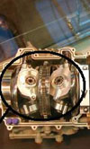
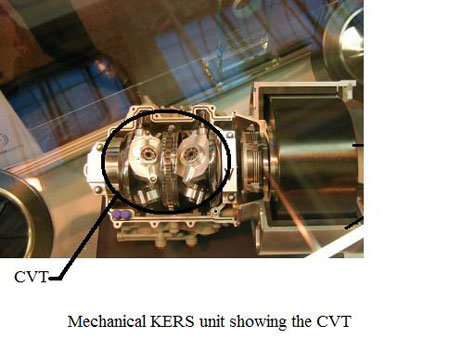
Fig. 1 - Mechanical KERS unit showing the CVT
Written by Eric Smart
5761