KERS: power electronics
Whenever we hear about Formula One KERS systems, or the much-vaunted hybrid systems as used at Le Mans and in a growing number of roadcars, many of us imagine a large alternator being used to change mechanical energy into electrical energy (or vice versa) and a battery for converting the electrical energy into chemical energy and provide short-term storage.
There is a third, very important, module that is part of a typical racing KERS system, and this is the power electronics. The aim here is to point out the reasons why we need power electronic modules, and look at what goes in inside one.
If you studied physics at school, you might have built a rudimentary electric motor. For a high-speed, high-torque electric motor, there is a requirement to turn the electromagnets on and off very quickly and accurately. If the point at which we choose to energise the electromagnet is calculated wrongly, we may produce lower than desired torque or possible zero or even negative torque. Just as engine torque reacts to changes in ignition timing, so motor torque reacts to changes in the 'timing' of energising the electromagnets.
Thinking back to that 'school physics motor' we probably switched the power to the coiled electromagnets via slip rings and brushes on the motor shaft. Brushed motors can cause problems at high levels of power transfer because of arcing, and also increase electrical noise, which can affect many of the other electrical systems on the car. If we wish to exercise accurate control of our motor/generator, we need to be in total control of the switching. In essence, the power electronics houses the high-current 'switches' and the electronic circuitry required for controlling these switches.
There are a number of devices capable of switching currents very precisely at high speed - two of these are the MOSFET (metal-oxide semiconductor field-effect transistor) and the IGBT (insulated gate bipolar transistor). There is a wealth of information available on both devices, but it is generally felt that MOSFETs are most suitable for low-current, low-voltage, high-speed switching, while IGBTs are more suited to high-voltage, high-current but lower speed switching.
In racing of course, we want to run the motors fast because, relative to a roadcar manufacturer, we place high value on the power density (power divided by package volume) of our system. A small electric motor that can produce or absorb a relatively modest torque at high speed can produce a very impressive amount of power for its size and mass. Typical electric motor/generators for hybrid race use have a power-to-mass ratio that is very similar to the highly developed race engine whose output they augment. When switching the power on and off to our motor's electromagnets, we want the speed of the MOSFET with the power capability of the IGBT. What we can end up with is an IGBT that struggles to cope and which is unreliable as a result. There are companies who are working on and promoting technology that can control high-power motors up to high rotational speed with a reduced rate of switching, bringing greater reliability to the IGBTs and the power electronics module.
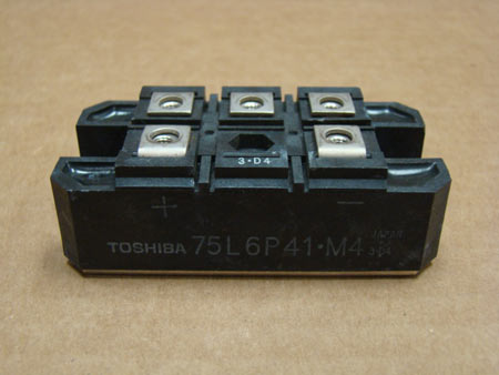
Fig. 1 - An IGBT is a high-power switching device, and is one of the key components in the power electronics module of an electric hybrid
Written by Wayne Ward
4352