Lead free bearing(s) fit
 In another article in this issue of RET-Monitor, I have given what I hope is an insight into crankcase main bearing split design (keyword: heads-blocks). Background is the accuracy of the main bearing split line geometry, primarily focused on the roundness of a main bearing bore.
Since the crankshaft system does not directly rotate in the bearing bore, we will look at the bearing shells in between. As John Coxon wrote in the May 2010 issue of Race Engine Technology
magazine (issue 46), in the past few years the 'End of Life' EU Directive has required that all lead be removed from the vehicle, no matter how small the amount. Where the Directive has 'supported' the automotive industry to develop lead-free type bearing materials, race engine designers have not yet transferred their focus to the lead-free alternatives. So let us look at what the areas of concern around lead-free bearing materials could be.
Bearing materials have their own specific properties regarding fatigue strength, rate of wear, corrosion resistance, conformability and embedability. In general, materials with harder, stronger properties are required for fatigue strength; softer properties are required for embedability and conformability.
The advantages of bearing shells containing lead are conformability and embedability. Particles can be 'bonded' into the softer material, and therefore do not lead to damage on the bearing shell and/or crankshaft. Conformability to local deformations with lead-containing bearings is less critical due to its soft mechanical properties. This article will therefore focus on the conformability aspect of the main bearing bore in relation to the lead-free alternative materials.
Conformability is typically shown on technical drawings with the cilindricity symbol and can be divided into two areas - shape and step.
The initial shape of the main bearing bore depends mainly on machining capability. In service, combustion and inertia loads will lead to deformations of the bore as well. Stiffness differences between cap and housing are significant parameters to achieve a homogeneous deformation, in order to be non-critical to the bearings.
Local steps can be characterised as sudden geometry changes over the bore diameter, and are mainly a consequence of damage or steps in the area of the split line. Local deformation in the area of the split line can consist of positioning tolerances during assembly of the bearing cap, where a positioning feature is typically used to align the cap with the crankcase.
Unfortunately, these positioning features require certain tolerances. Measurements have shown that a so-called cracked main bearing is dimensionally more stable over the split line in comparison to more traditional positioning methods such as pins, bushes or machined positioning surfaces.
After assembly of the bearing shells, the resulting roundness at the level of the split line remains a focus of attention during the running-in phase of the engine (and its bearing shells). During assembly, the slightly proud standing bearing shells are pre-tensioned, which will result in a radial force on the bearing bore geometry (called 'crush').
Depending on the stiffness differences between housing and bearing shells, a certain resulting geometry will be 'set'. To achieve sufficient clearance at the split-line location, the bearing ends are often tapered to some extent, creating a more or less oval resulting geometry.
The intersection between the tapered geometry and the nominal diameter of the bearing shell is the next critical zone. Contact between crankshaft and bearing shell edge can lead to local contact and initial wear of both components. Lead-free bearings with, for example, a lead-free bronze intermediate layer are significantly harder and therefore have less conformability, so bearing shell suppliers provide running-in layers on the bearing surface, with thicknesses of the order of 0.0001", to give significant improvements in the conformability behaviour of the bearing.
Ultimately, the 'End of Life' Directive will not miss out on motorsports. Given the need for it to become more eco-friendly, the race engine industry will need to work in accordance with the Directive. But questions remain as to which developments in lead-free bearing materials can be carried over from the regular automotive industry.
Although circumstances in race engine technology might be different from the roadcar industry, with additional developments on the structure and design of the main bearing area - as well as on bearing materials - it should be possible to make significant steps towards the widespread use of lead-free bearing materials. Who will be first though, and thus prove a winner?
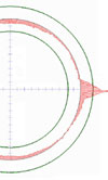
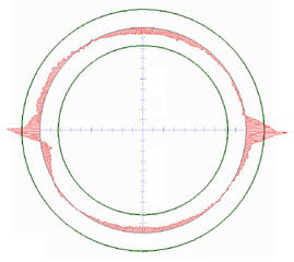
Fig.1 - Roundness measurement of a main bearing bore
Written by Dieter van der Put