Lifters
 For those who have no interest in pushrod engines in racing, their criticism of categories such as NASCAR, and the engines used, revolves around a perceived lack of technology. The regulations for the Sprint Cup series in certain areas don't help dispel this perception, mandating flat-faced lifters to be used in bespoke race engines when all modern pushrod production engines have turned to using roller lifters. In racing too, where choice of roller type isn't restricted, the flat lifter is generally shunned in favour of the roller type.
Roller lifters are more complex and have moving parts, but offer better engine performance due to the extra latitude given to development engineers in designing new valve lift profiles. The diameter of a flat lifter limits the opening and closing velocities of the lift profile according to the formula:

where r is the radius of the lifter, and w is the width of the cam lobe. Note that the formula assumes that the lifter bore intersects the camshaft axis, and that the middle of the lobe width is coincident with the lifter bore axis.
This is the same limitation which designers of overhead cam engines find when using flat tappets. This limitation can lead to unconventional valve acceleration profiles in order to maximise the air-flow into the engine.
Engines, while appearing to be very stiff, naturally move about under load and at temperature. Race engines are highly loaded, and high loads lead to greater deflections. In the case of the flat-faced lifter, camshaft and block deflections mean that the cam can be slightly misaligned relative to the lifter bore. This can lead to 'edge' loading of the cam - that is, where the theoretical line contact between cam and lifter is replaced by a point contact between the lobe edge and the lifter. This situation can cause premature damage to the face of the lifter.
There are a couple of design features that can improve the chances of the lifter not failing due to locally high contact stresses. The first is to carefully deburr the edges of the cams, replacing the sharp edge with a small radius. This does much to limit the contact stress. The second is to add a very slight dome to the flat face of the lifter. This gives no advantage in terms of increasing the available lift velocity, but means that the camshaft and lifter can accommodate a reasonable degree of dynamic distortion without edge loading being a factor.
Of course, this means that the contact is designed to be a point contact, but with the cam being flat and the follower having a very large dome radius, the contact stresses are not too high. The 'height' of the dome (measured from the edge of the flat surface to the top of the dome) is very small, and likely to be less than one thousandth of an inch.
Mechanically, the flat-faced lifter is simple, although it is a little more complex than the analogous flat tappet of an overhead cam engine. In many cases it has to transfer pressurised oil to the bore of the hollow pushrod in order to provide lubrication to the contact between the pushrod and rocker.
As we know, valvetrain stiffness is critical, and this is one area where the flat-faced lifter is superior to the roller lifter. With no bearings, shafts or shaft supports - all of which deflect to a greater or lesser extent - the flat-faced follower is much stiffer in compression.
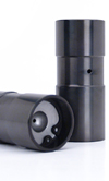
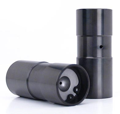
Fig. 1 - Flat lifters, as might be found in a Sprint Cup engine (Courtesy of Comp Cams)
Written by Wayne Ward