Liner Distortion
 Spare a thought for the poor cylinder liner. As well as expecting it to be perfectly round from the outset, we then go on to expect it to remain so throughout the rest of its life, and under the most arduous conditions.
But are we making it as round as it could be? Take for instance the typical case of a replacement dry liner. We'll measure its external diameter in at least three positions around its axis, and then again in another three places up and down the bore. Averaging these and allowing something like 0.001 in per inch diameter of interference, we'll happily bore away, taking care of squareness and roundness of the boring head until we finally have any number of liners firmly seated in the block. This, however, is only the starting point.
The thin metal liner may have been distorted from careless handling (such as leaving it lying on its side for a long time instead of upright) but no matter what its initial shape, in the end it will conform to the shape of the hole into which it was pushed. Too little interference and the thing will just rattle around in use; too much and the surface could end up being convoluted and even more distorted. Ever tried to get one of those plastic wiring grommets through a hole that was too small for it? Well the situation is much the same here, except that the forces are so great that in the process the edges of the liner could even be damaged.
Often it's a case of 'suck it and see' and for each engine the machine shop will find a way that works for them. But whichever way you look at it, further machining/honing will be necessary.
For anyone concerned about the clamp loads from the cylinder head, a boring plate will be needed. This consists of a metal plate of equivalent stiffness to the actual cylinder head, with holes drilled through it above the bores to enable access by the boring bar/honing tool, and should be clamped into place - ideally using the similar bolts to those used in service - and tightened into yield using the same torque and angle values. This should simulate the loads introduced at build.
In addition, and to get even closer, a similar gasket/fire ring arranged should be inserted to replicate the real geometry at the head face. While many good quality machine shops will use a simple 1 in-thick boring plate, it is always difficult to know how representative such a plate might be. In using similar geometries and actual components as far as is practicable, the loads should be closer to those encountered in use.
But what about the thermal input, I hear you ask? Won't that cause distortion as well? Unsurprisingly, the best machine shops have thought about this and it's not uncommon for them to use hot oil circulating through the cylinder block during final machining. The oil will allow temperatures of up to 150º C, perhaps more if you really want, but I would have thought 100-120º C would be enough of a problem - after all, some poor machinist may have get close to it at some time.
But despite all this, are we not forgetting the effect of combustion pressure on all this distortion? Perhaps we need to introduce nitrogen at high pressure to the cylinder bore which, when sealed top and bottom, will use a specialised boring head. I haven't heard of anyone doing this as yet - although that doesn't mean it hasn't been done - and the pressure couldn't be anywhere near that encountered in a fired engine. Hang on a minute though, am I not taking this to the extreme?
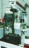
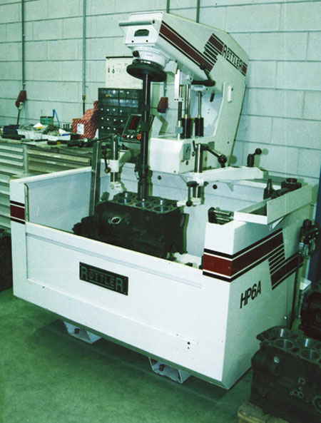
Fig. 1 - Bore preparation the traditional way
Written by John Coxon
2917